
Heat sink

A radiator and heat sink technology, applied in the field of radiators, can solve the problems of equipment burnout and low efficiency of electrical equipment, and achieve the effects of improving thermal power efficiency, improving heat dissipation effect, and improving thermal power effect.

Inactive Publication Date: 2010-10-06
ABB TECH AG
View PDF2 Cites 4 Cited by
  • Summary
  • Abstract
  • Description
  • Claims
  • Application Information

AI Technical Summary

Problems solved by technology

If the heat cannot be effectively dissipated, the efficiency of electrical equipment will be very low, and the equipment may be burned out.

Method used


Image

  • Heat sink
  • Heat sink
  • Heat sink

Examples


Embodiment Construction

[0018] Embodiments of the present invention will be described in more detail below in conjunction with the accompanying drawings of the present invention.

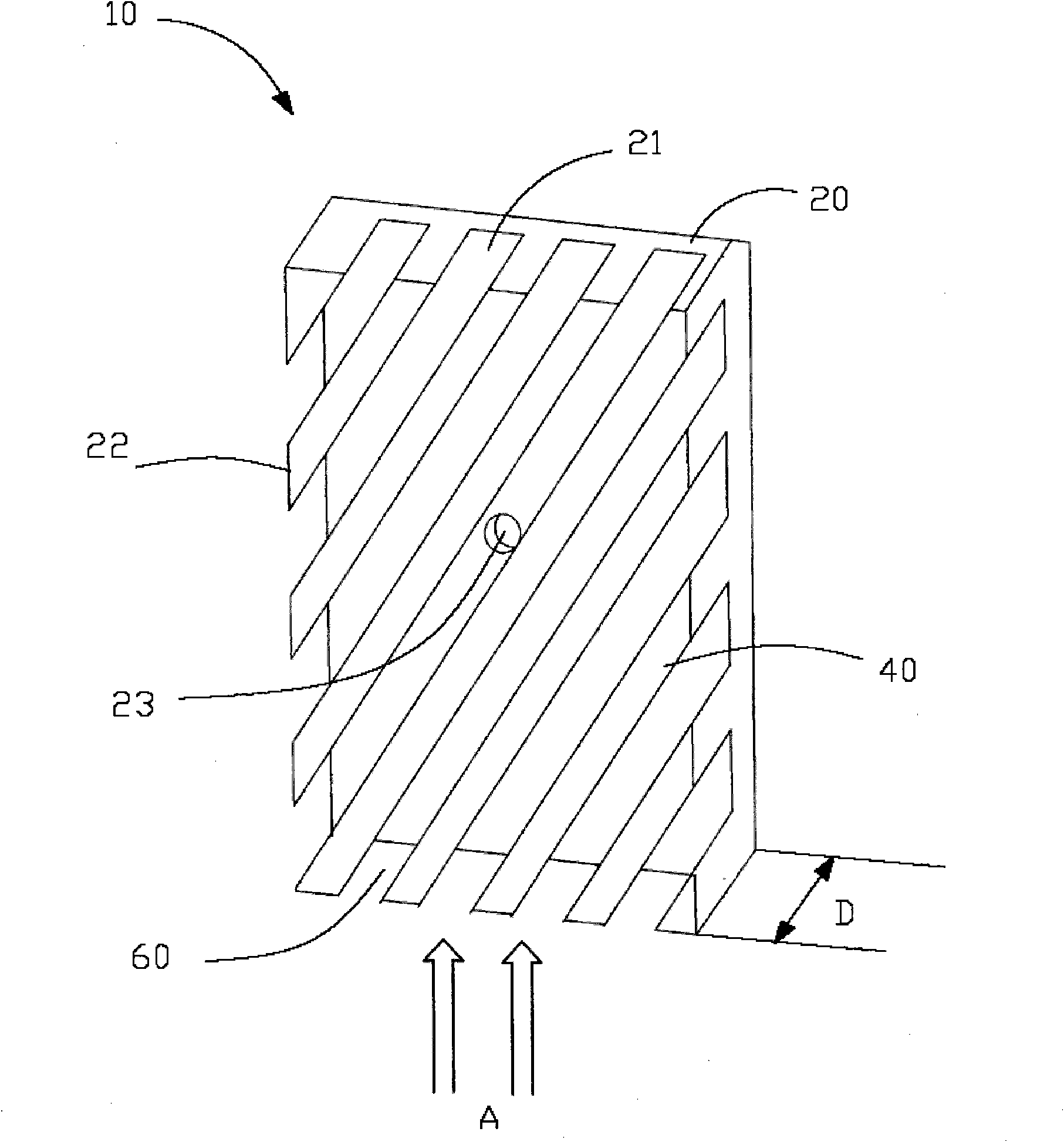
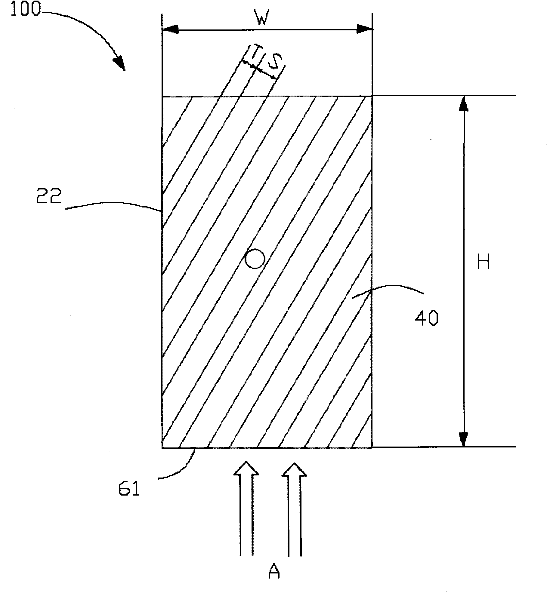
[0019] figure 1 and figure 2 One embodiment of the heat sink 10 of the present invention for removing heat from an electrical device is shown. figure 1 is a perspective view of the radiator of this embodiment, figure 2 is a plan view of the radiator of this embodiment.

[0020] Such as figure 1 and figure 2 As shown, a heat sink 10 for dissipating heat from an electrical device such as a switchgear, a circuit breaker or a transformer (not shown) comprises: a base 20 having a flat top surface 21 and sides 22; a plurality of heat sink fins 40 is disposed on the flat top surface 21 of the base 20 , the extension direction of the plurality of heat sink fins 40 is inclined to the inflow direction A of heat flow; and a channel 60 formed by every two adjacent heat sink fins 40 . The inflow direction A is the direction in...


PUM


Abstract

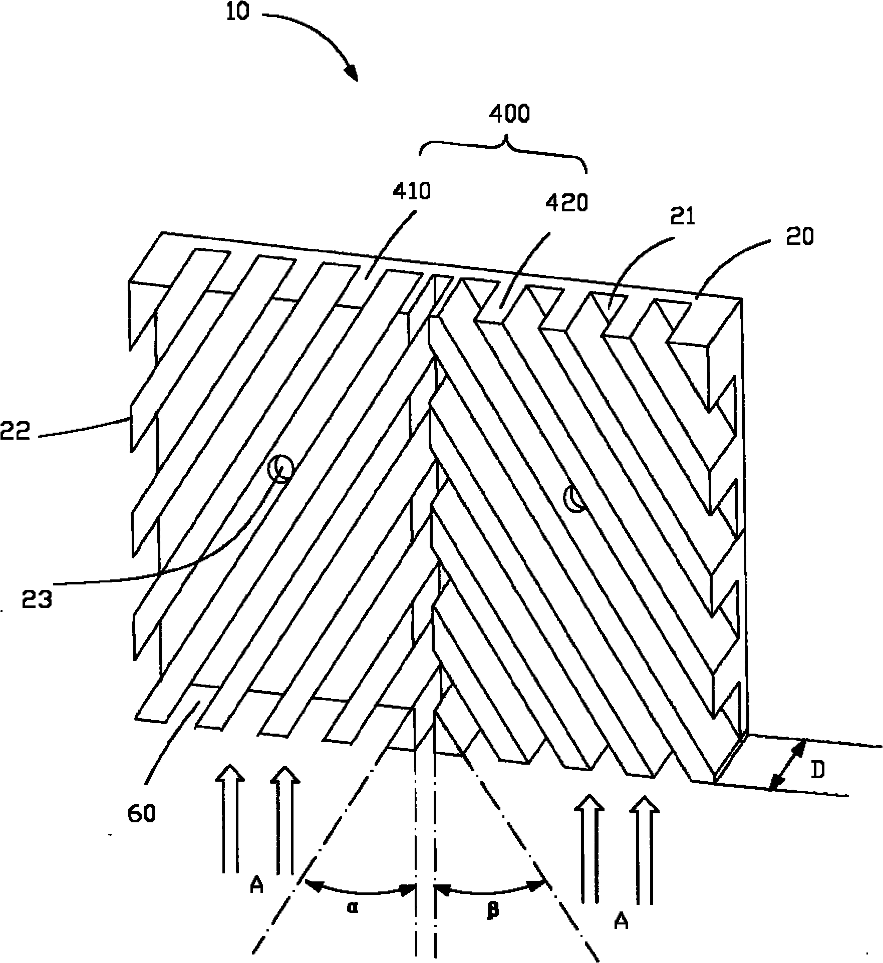
A heat sink (10, 100) for dissipating heat from an electrical device comprises a base (20) having a generally flat top surface (21); a plurality of fins (40, 400) arranged on the top surface (21) of the base (20) such that a running direction of the fins (40, 400) is oblique to an in-flow (A) of heat flow; and a plurality of channels (60) defined between each two adjacent fins (40, 400).

Description

technical field [0001] The present invention relates to a heat sink for removing heat from electrical equipment such as switchgears, circuit breakers and transformers. Background technique [0002] Electrical equipment such as switchgear, circuit breakers and transformers generate a lot of heat during operation. If the heat cannot be effectively dissipated, the efficiency of the electrical equipment will be very low, and the equipment may be burned out. Therefore, radiators have become an indispensable part of modern electrical equipment. Moreover, how to provide an effective heat sink has also become a hot topic in the field of electrical industry. [0003] Various heat sinks for dissipating heat generated by electrical equipment have been proposed, examples of which can be found in US Patent Application Publications US 2004141290 and US 2008144279. The radiator proposed in the US patent application US 2004141290 includes a base and a plurality of fins parallel to each o...

Claims


Application Information

Patent Timeline
Patent Type & Authority Applications(China)
IPC IPC(8): H01L23/367H05K7/20G06F1/20
CPCH01L23/3672H01L2924/0002
Inventor 涂占炜胡标李春朱奎奎
Owner ABB TECH AG
Learn More