Motor control device and control method thereof

A motor control and motor technology, applied in the direction of controlling electromechanical transmissions, controlling electromechanical brakes, control systems, etc., can solve the problems of not increasing speed, poor efficiency, and inability to generate torque.

Inactive Publication Date: 2013-07-31
YASKAWA DENKI KK
View PDF3 Cites 14 Cited by
  • Summary
  • Abstract
  • Description
  • Claims
  • Application Information

AI Technical Summary

Problems solved by technology

[0042] In the field weakening control of the existing motor control device, the maximum voltage is set in advance, and the d-axis current command is corrected by making the voltage command consistent with this value, so the DC bus voltage V of the power conversion circuit such as a battery DC In the case of fluctuations, the maximum voltage that can be output by the PWM inverter may differ from the maximum voltage set, and it may not be able to fully function
That is, for the set maximum voltage, if the DC bus voltage V DC Decrease, the voltage is saturated and cannot generate torque, so that the speed does not increase, on the contrary, if V DC If the voltage is higher than the assumed voltage, there is a problem that the efficiency is not good because the current flows although there is a margin in the voltage.
In addition, because the calculation is based on the deviation from the maximum voltage, it is necessary to set the maximum voltage lower than the maximum voltage that the PWM inverter can output. bad question
[0043] In addition, in the method of detecting voltage saturation, there is a problem that the responsiveness of field weakening control changes due to changes in the rotation speed or power supply voltage.
[0044] In addition, the method of using the phase error command value at the time of voltage saturation has the following problems. Since switching control is required, complex processing is required, and it is assumed that a motor that does not use reluctance torque such as a surface-mounted permanent magnet synchronous motor (SPMSM) , so it is difficult to apply to motors using reluctance

Method used


Image

  • Motor control device and control method thereof
  • Motor control device and control method thereof
  • Motor control device and control method thereof

Examples


Embodiment 1

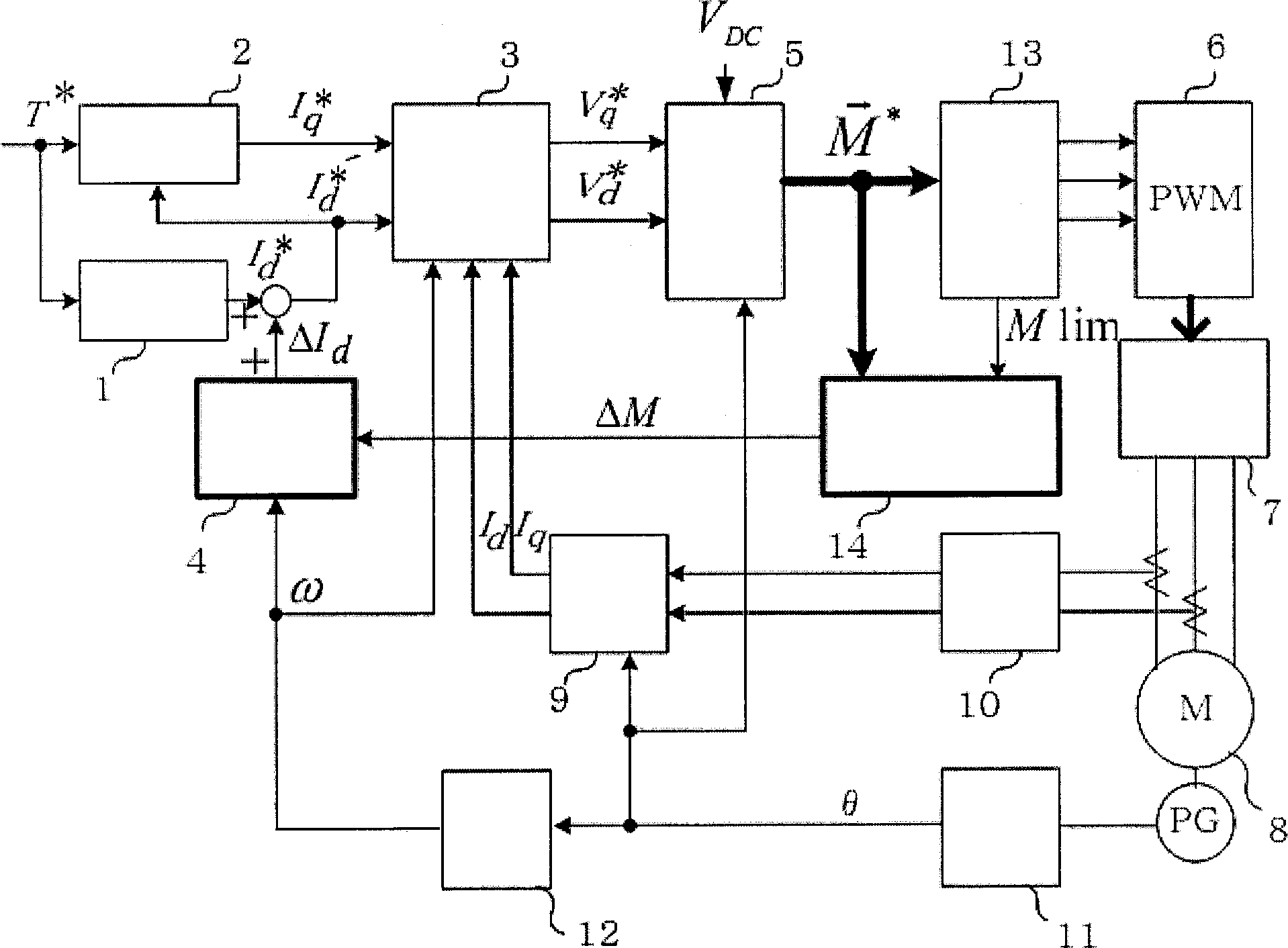
[0093] figure 1 It is a control block diagram showing an example in which the motor control device of the present invention is applied to a three-phase interior permanent magnet synchronous motor (IP MSM).

[0094] The d-axis current command calculation unit 1 inputs the torque command T*, and calculates the most suitable d-axis current command I according to the characteristics of the motor d *. The q-axis current command computing unit 2 inputs the torque command T* and the d-axis current command I d *, and calculate the q-axis current command I q *. The current command computing unit is constituted by the d-axis current command computing unit and the q-axis current command computing unit. The current control unit 3 inputs a dq-axis current command and a dq-axis current detection value, and obtains a voltage command by matching the dq-axis current detection value with the dq-axis current command. Current control generally consists of separate PI control and voltage FF c...

Embodiment 2

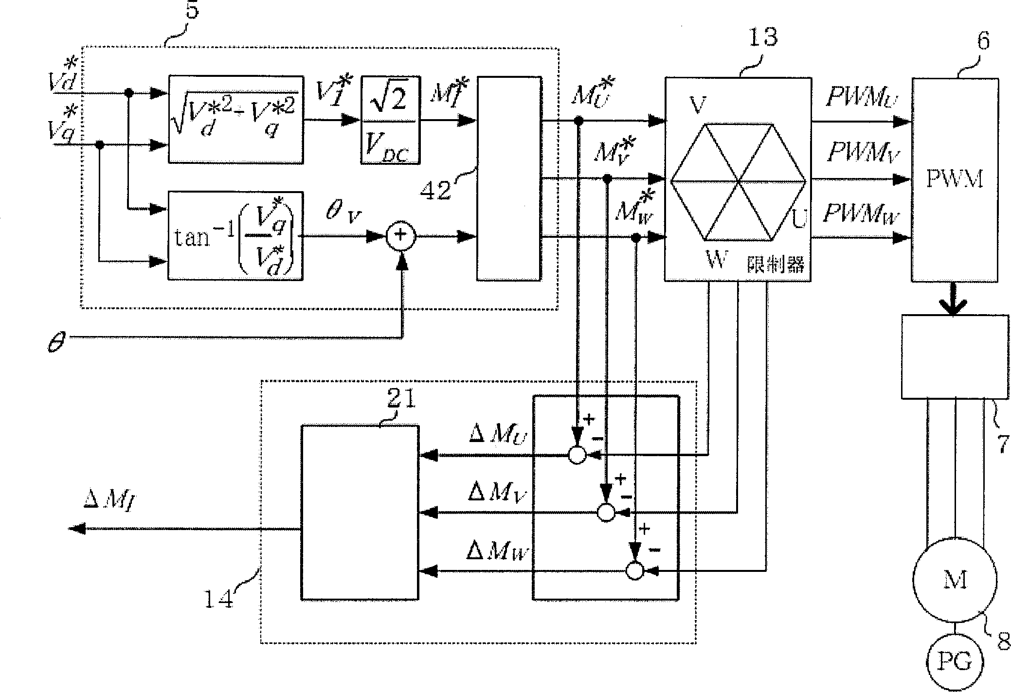
[0132] Figure 4 It is a block diagram showing the modulation wave command calculation unit 5, the modulation wave command restriction unit 13, and the modulation factor saturation calculation unit of the second embodiment. The modulated wave command calculation unit 5 obtains the modulation factor M from the dq axis voltage command I and output phase θ 0 On this point, it is the same as that described in Example 1 figure 2 same. The difference is that the modulation rate instruction M I and output phase θ 0 As the first modulated wave command, in the modulated wave command limiting unit 13, the modulation rate limiting unit 41 sets the modulation rate limit value M 1imit Limit modulation rate command M I And the second modulation rate command M' is obtained I , using the second modulation rate command M’ I and output phase θ 0 In the three-phase conversion unit 42 , the second modulated wave command for the three phases is obtained as follows, for example, as in Equ...

Embodiment 3

[0139] Figure 5 It is a block diagram showing the modulation wave command calculation unit 5, the modulation wave command restriction unit 13, and the modulation factor saturation calculation unit of the third embodiment. The modulated wave command calculation unit 5 obtains the modulation factor M from the dq axis voltage command I , the dq-axis voltage command and the modulation rate M I As the first modulation wave command. In the modulated wave command limiting unit 13, the modulation rate limits the value M 1imit Limit modulation rate M I And find M' I , in the dq modulated wave instruction computing unit 51, by M' I The modulated wave command M of the dq axis is obtained as follows with the dq axis voltage command d , M q .

[0140] V 1 = V d * 2 + V q ...


PUM


Abstract

A motor control device which always operates at a maximum voltage even if a DC mother line voltage of a power conversion circuit changes and is made highly efficient, and its control method are provided. The motor control device having a d, q-axes current instruction operation section (1, 2), a dq-converter (9), a current controller (3), a modulated wave instruction operation section (5) and a PWM generator (6) has a modulated wave instruction limiter (13) which limits a first modulated wave instruction and generates a second modulated wave instruction, a modulation rate saturation degree operation section (14) which obtains a modulation rate saturation degree from the first modulated wave instruction and a limit value of the modulated wave instruction limiter, and a weak field controller (4) which corrects a d-axis current value on the basis of the modulation rate saturation degree.

Description

technical field [0001] The present invention relates to a motor control device that performs field weakening control when the voltage of the motor is saturated. Background technique [0002] Although the induction voltage of the motor increases according to the speed, if the voltage command is saturated for the power supply, the torque cannot be generated and the speed does not increase, but the torque can be generated by reducing the d-axis current command, and the speed control range can be expanded. In the case of an induction motor, as a d-axis current accompanying a magnetic flux command within a normal range, if voltage saturation is encountered, the d-axis current is reduced. In a surface-mounted permanent magnet synchronous motor (S PMSM), the d-axis current is usually made to be 0, and a negative d-axis current is made to flow within the voltage saturation range. In an interior permanent magnet synchronous motor (IPMSM), a negative d-axis current flows in a normal ...

Claims


Application Information

Patent Timeline
Patent Type & Authority Patents(China)
IPC IPC(8): H02P21/00H02P6/08H02P27/04H02P21/22H02P25/026H02P27/08
CPCH02P21/06H02M2007/53876H02P21/0089H02M7/53876Y02P80/10
Inventor 森本进也高木护
Owner YASKAWA DENKI KK
Why Eureka
Try Eureka