Two-stage foot braking master valve

A brake master valve and spot brake technology, applied in the field of automobile brake master cylinder, can solve the problems of affecting the suspension system, carbonization, affecting the braking effect, etc.

Inactive Publication Date: 2010-10-13
CHANGTONG TECH
View PDF6 Cites 30 Cited by
  • Summary
  • Abstract
  • Description
  • Claims
  • Application Information

AI Technical Summary

Problems solved by technology

[0002]The existing standard brake master valve has weak braking force and cannot control the braking distance well under heavy load; there is also heavy rebound force of the control pedal, This shortcoming directly affects the operating comfort, and will increase the driver's physical exertion and other shortcomings.
[0003] In order to improve the above shortcomings, people invented a "light-load powerful master cylinder". This technology has significantly improved th

Method used


Image

  • Two-stage foot braking master valve
  • Two-stage foot braking master valve
  • Two-stage foot braking master valve

Examples


Embodiment

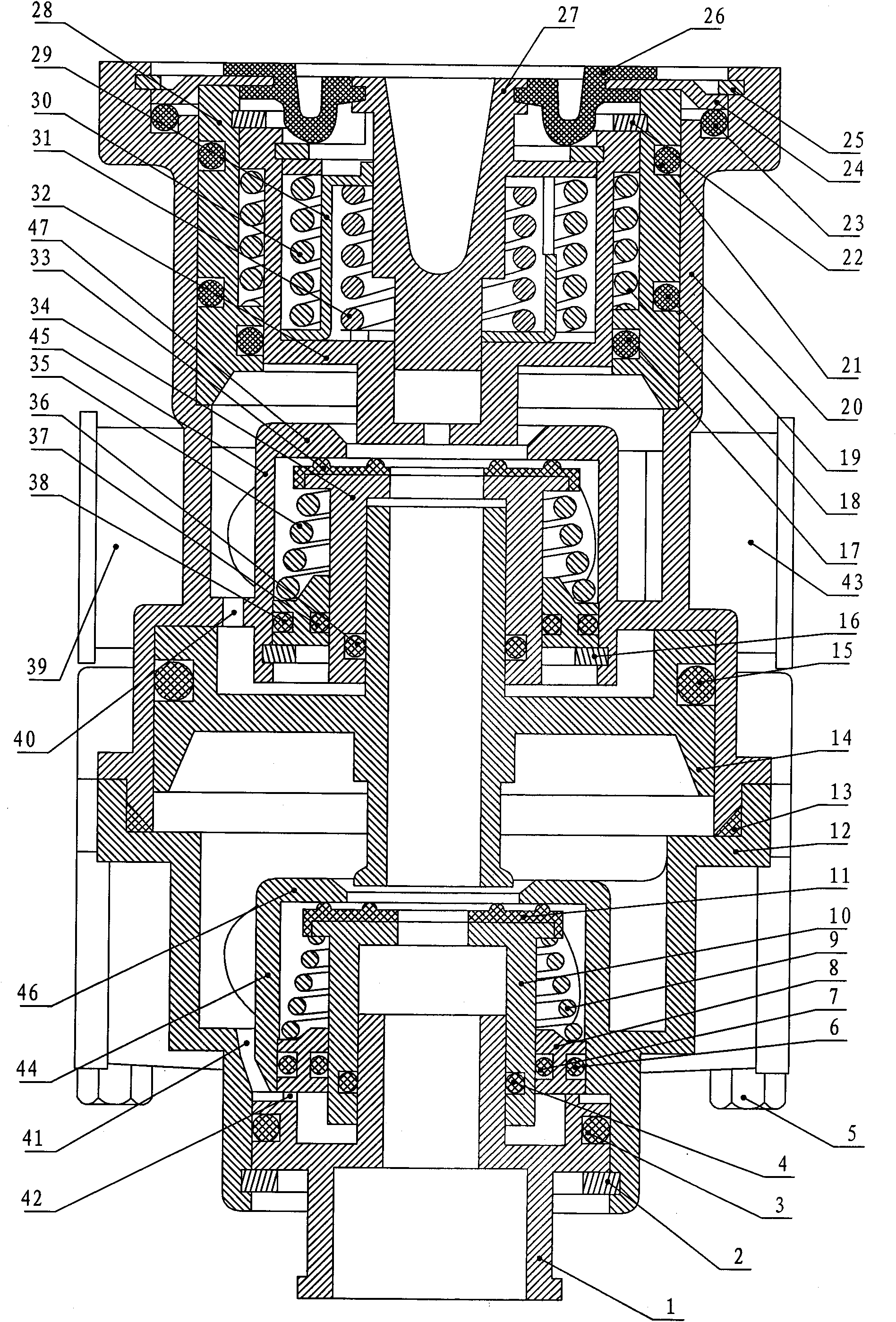
[0027]Embodiment: a kind of two-stage point braking master valve (type I), which contains an upper valve body and a lower valve body, and the upper valve body and the lower valve body are all provided with an air inlet hole and an air outlet hole, the described The lower edge of the upper valve body is inserted into the upper edge of the lower valve body, the upper piston assembly is installed in the upper part of the upper valve body, the upper valve assembly is installed in the middle of the upper valve body, and the lower valve assembly is installed in the lower valve body. The valve assembly, the upper and lower valve assemblies are driven by the lower piston installed in the lower part of the upper valve body. The spring and the clip pad are fixedly installed in the stepped hole on the upper part of the upper valve body. The upper piston is installed in the piston sleeve through the snap ring. The upper piston is a piston with a cavity inside. The outer surface of the uppe...


PUM


Abstract

The invention relates to a two-stage foot braking master valve (I type) which comprises an upper valve body and a lower valve body, wherein both the upper valve body and the lower valve body are provided with an air inlet hole and an air outlet hole, the lower edge of the upper valve body is inserted into the upper edge of the lower valve body, an upper piston assembly is installed at the upper part in the upper valve body, the upper piston assembly comprises a piston bush, an upper piston, a spring package clip and an ejector pin seat, the inside and the outside of the spring package clip are respectively provided with a pressure intensity spring and a steady pressure spring, a certain distance is reserved between the upper part of the pressure intensity spring and the lower surface of the wide disc of the ejector pin seat, and the distance enables the valve to produce a secondary pressure intensity to quickly and powerfully combine a brake block and a brake drum so as to maintain a favorable combination condition all the time and ensure a favorable brake effect all the time. Simultaneously, the friction between the brake block and the brake drum can be decreased to the greatest extent, and the brake block can be prevented from being carbonized so as to prolong the service life of the brake.

Description

1. Technical field [0001] The invention relates to an automobile brake master cylinder, in particular to a two-stage point brake master valve (Type I). 2. Background technology [0002] The existing standard brake master valve has weak braking force and cannot control the braking distance well under heavy load; there is also heavy rebound force of the control pedal, which directly affects the operating comfort and increases the driver's Disadvantages such as physical exertion. [0003] In order to improve the above shortcomings, people invented a "light-load powerful master cylinder". This technology has significantly improved the above shortcomings, but it also has many defects. Under the same conditions, it is easier to damage the accessories of the brake system, such as brake pads, brake drums, pipe fittings, etc., which will affect the suspension system. The rapid heating will lead to carbonization, which will directly affect the braking effect. If the braking is too f...

Claims


Application Information

Patent Timeline
IPC IPC(8): B60T15/42
Inventor 田青锋
Owner CHANGTONG TECH
Why Eureka
Try Eureka