Knife for air splicing device

A splicer and cutter technology, applied in the field of cutters for air splicers, can solve the problems of cutter breakage and insufficient sharpness of ordinary cutters, and achieve the effect of excellent sharpness and service life

Inactive Publication Date: 2010-10-13
SHANGHAI KAILI TEXTILE HARDWARE
View PDF0 Cites 0 Cited by
  • Summary
  • Abstract
  • Description
  • Claims
  • Application Information

AI Technical Summary

Problems solved by technology

[0003] In order to solve the technical problem of insufficient sharpness of ordinary knives and even broken knives when the air splicer in the prior art is splicing special yarns, the present invention provides a knives for air splicers, which can better complete air splicing cutting of special splicing yarns

Method used


Image

  • Knife for air splicing device
  • Knife for air splicing device
  • Knife for air splicing device

Examples


Embodiment Construction

[0011] The present invention will be further described below in conjunction with the accompanying drawings.

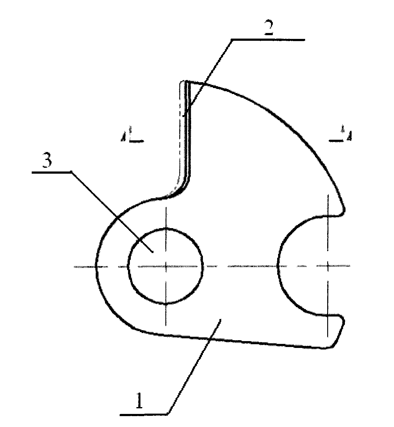
[0012] Such as figure 1 As shown, the structure schematic diagram of the fixed cutter used by the air splicer of the present invention includes a cutter body 1 and a knife edge 2, and the cutter is fixed on the splicer through the positioning hole 3 on the cutter body 1, and the knife edge 2 is a knife edge of 10° to 20° structure.

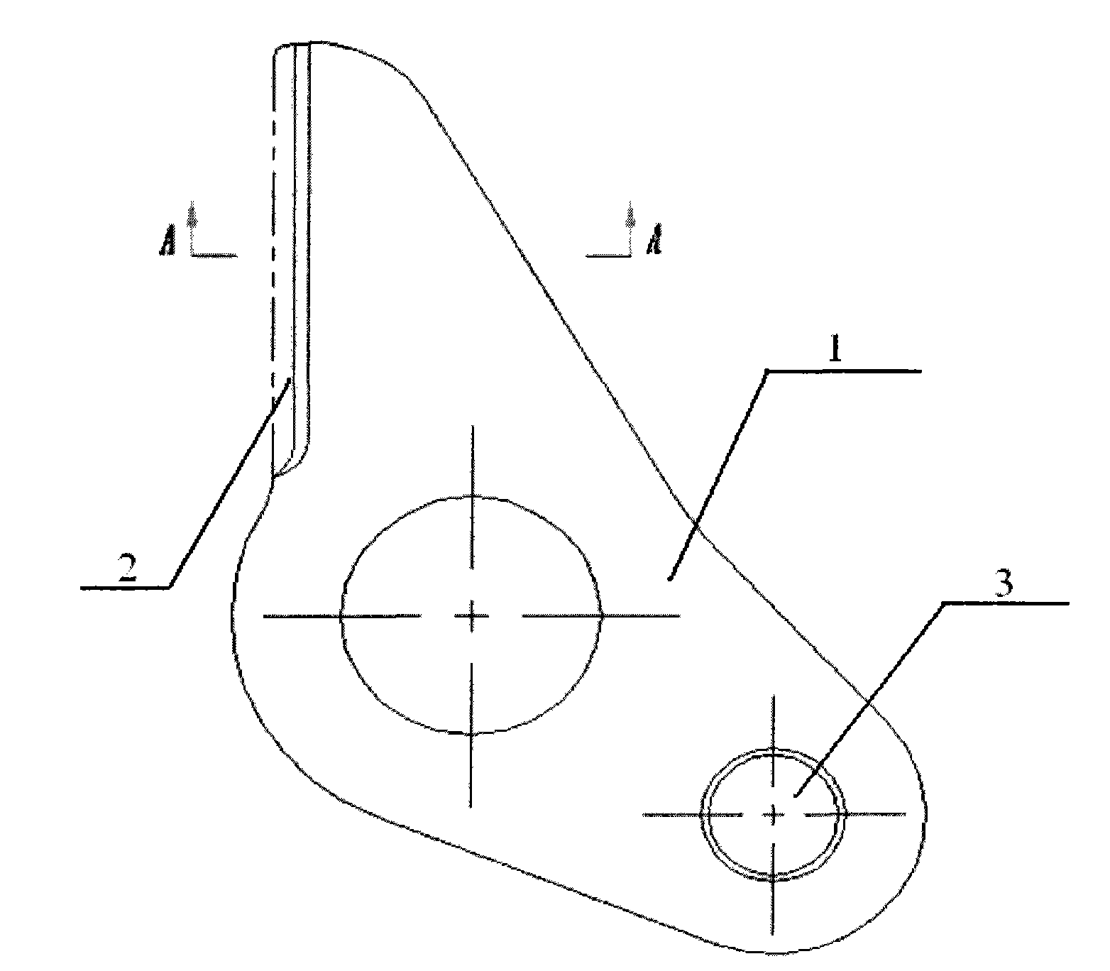
[0013] Such as figure 2 As shown, the schematic diagram of the structure of the movable cutter for the air splicer of the present invention includes a cutter body 1 and a knife edge 2, and the cutter is installed on the splicer through the positioning hole 3 on the cutter body 1, and the knife edge 2 is a knife edge of 10° to 20° structure.

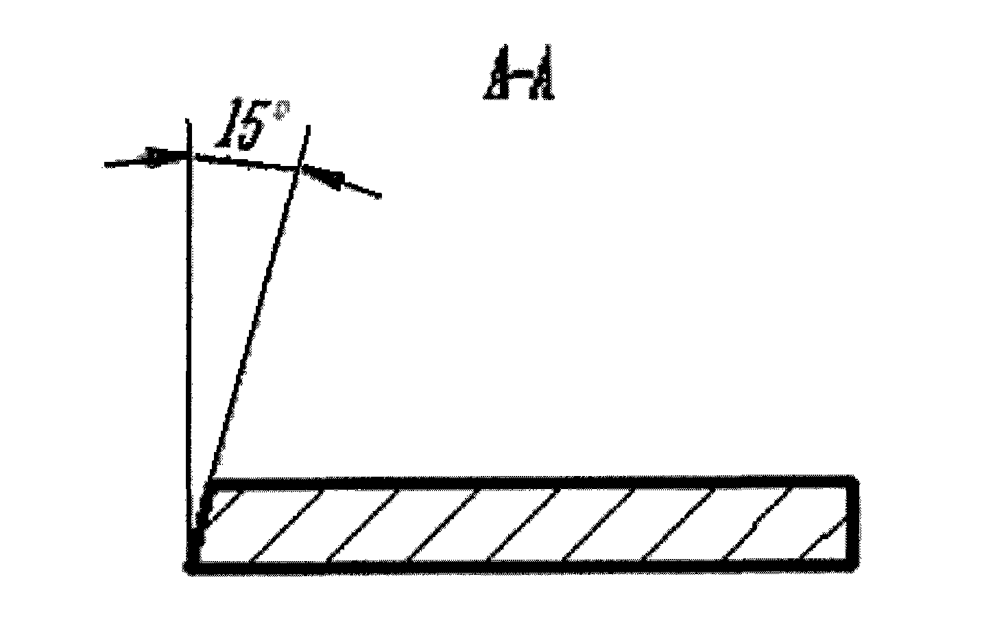
[0014] Such as image 3 As shown, the knife edge structure schematic diagram of the air splicer tool of the present invention, the structure of the knife edge is 15°.


PUM


Abstract

The invention provides a knife for an air splicing device, which comprises a knife body and a blade. The knife body is provided with a positioning hole. The structure of the blade is 10 to 20 degrees. With the invention, the air splicing device can better cut the special spliced yarns and the tartness and the service life of the knife are better than the common knife.

Description

technical field [0001] The invention relates to a cutter, in particular to a cutter for an air splicer. Background technique [0002] The cutter of the air splicer is an important part of the splicer, and the cutting of the spliced ​​yarn is realized by the cutter. For the special yarn spliced ​​by the splicer, such as coarse yarn, thick wool, ion cloth, etc., the common knife will not be sharp enough during cutting due to insufficient sharpness, and even the knife may be broken. Therefore, the splicer for splicing special yarns needs to be assembled with a tool that can not only meet the cutting sharpness, but also ensure the service life. Contents of the invention [0003] In order to solve the technical problem of insufficient sharpness of ordinary knives and even broken knives when the air splicer in the prior art is splicing special yarns, the present invention provides a knives for air splicers, which can better complete air splicing cutting machine for special spl...

Claims


Application Information

Patent Timeline
Patent Type & Authority Applications(China)
IPC IPC(8): D01H15/00D01H13/00D06H7/00
Inventor 王仲乐於国夏黄志铭
Owner SHANGHAI KAILI TEXTILE HARDWARE
Why Eureka
Try Eureka