Blower impeller
A blower and impeller technology, applied in the direction of mechanical equipment, machines/engines, liquid fuel engines, etc., can solve the problems of air volume performance deterioration, productivity reduction, resin molding difficulty, etc., to achieve air supply performance, suppress the increase of turbulent noise, Effect of suppressing deterioration of productivity
- Summary
- Abstract
- Description
- Claims
- Application Information
AI Technical Summary
Problems solved by technology
Method used
Image

Examples
Embodiment approach 1
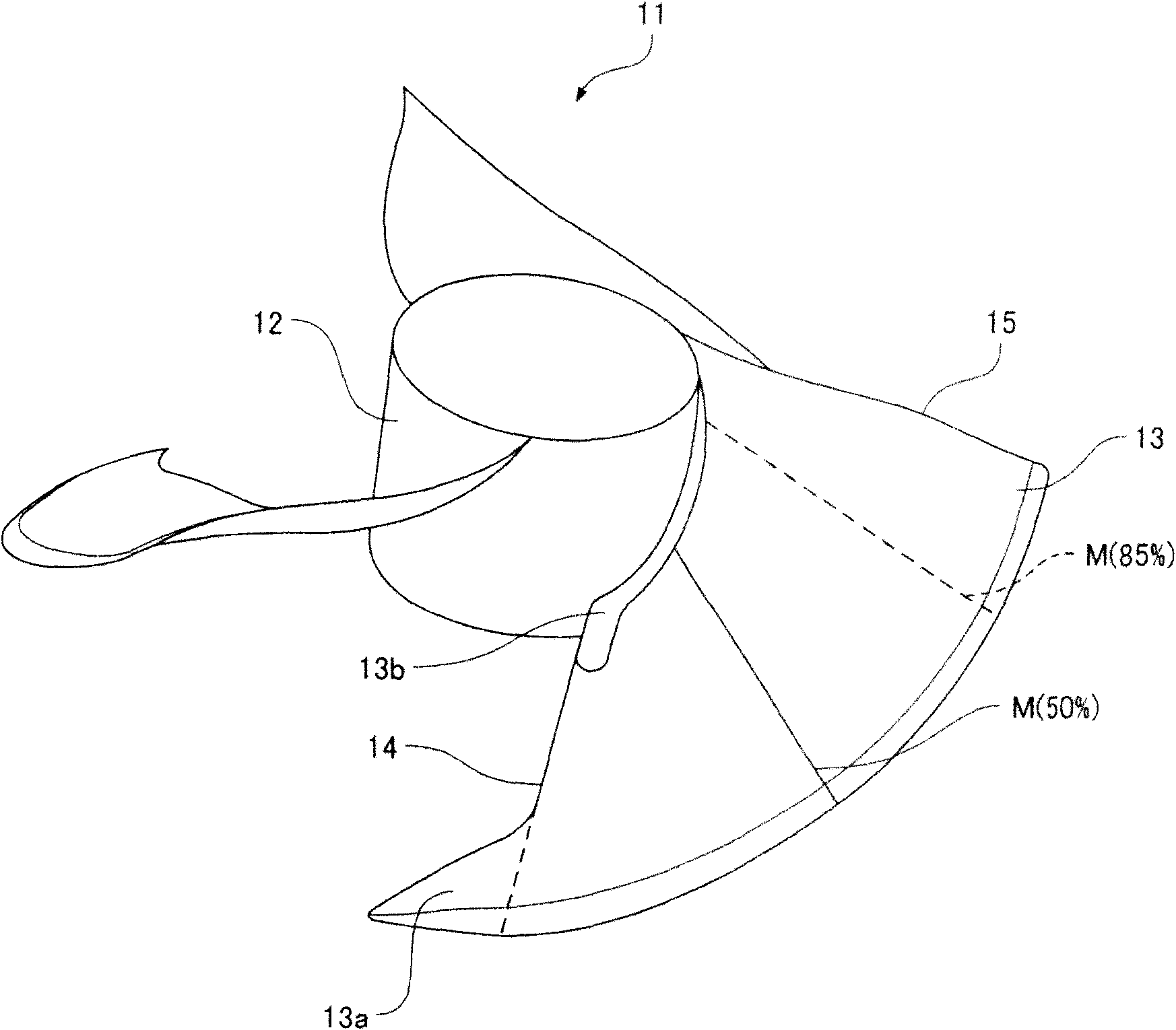
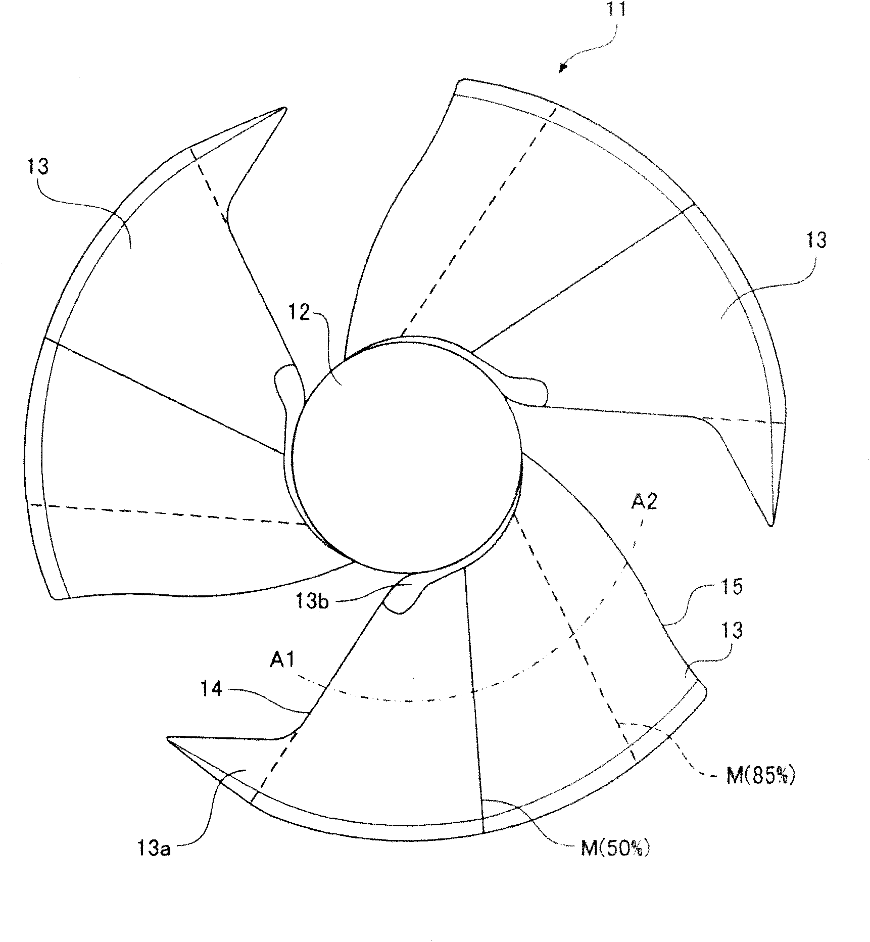
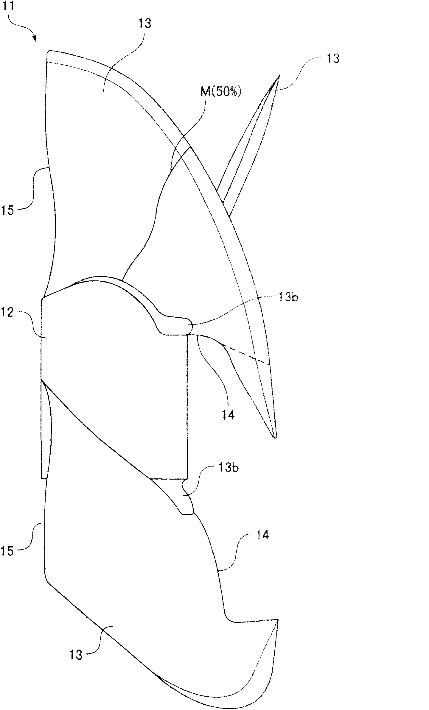
[0029] figure 1 It is a perspective view of the blower impeller according to Embodiment 1 of the present invention, showing the side and front of the blower impeller. figure 2 It is a side view of the blower impeller according to Embodiment 1 of the present invention, image 3 It is a front view of the blower impeller according to Embodiment 1 of the present invention. in addition, Figure 4 and Figure 5 means roughly along the figure 2 The cross-sectional shape of the blade in the circumferential direction of the blade is shown along the equal flow lines A1-A2.
[0030] Such as Figure 1 to Figure 3 As shown, the blower impeller 11 includes a substantially cylindrical hub 12 and a plurality of (three) blades 13 arranged around the hub 12 and extending radially from the hub 12 . In addition, in the first embodiment, the hub is made into a cylindrical shape, but the shape of the hub is not limited to the cylindrical shape, for example, a truncated cone shape, a combin...
Embodiment approach 2
[0040] Figure 6 It is a perspective view of the blower impeller according to Embodiment 2 of the present invention, showing the side and front of the blower impeller. Figure 7 It is a front view of the blower impeller according to Embodiment 2 of the present invention. Components corresponding to components already described in Embodiment 1 above are denoted by the same reference numerals, and detailed description thereof will be omitted.
[0041] The cross-sectional shape in the circumferential direction of each blade 13 included in the blower impeller 11 is the same shape as that in the first embodiment described above. That is, the region from the leading edge 14 to the position M of each blade 13 is formed in an airfoil shape. In addition, the region from the position M to the trailing edge 15 of each blade 13 is formed in a shape with a constant thickness ( t1 = t2 ).
[0042] In the blower impeller 11, as Figure 6 , Figure 7 As shown, the thickness of the root p...
PUM
 Abstract
Description
Claims
Application Information
 - R&D
- Intellectual Property
- Life Sciences
- Materials
- Tech Scout
- Unparalleled Data Quality
- Higher Quality Content
- 60% Fewer Hallucinations
Browse by: Latest US Patents, China's latest patents, Technical Efficacy Thesaurus, Application Domain, Technology Topic, Popular Technical Reports.
© 2025 PatSnap. All rights reserved.Legal|Privacy policy|Modern Slavery Act Transparency Statement|Sitemap|About US| Contact US: help@patsnap.com