
LED luminescent unit and motorcycle LED headlamp light source thereby

A light-emitting unit and LED lamp bead technology, applied in the field of LED light sources, can solve problems such as unreachable, poor heat dissipation, and easy breakage, and achieve the effects of improving the utilization rate of light, widening the illumination range, and facilitating safe driving.

Inactive Publication Date: 2010-10-13
重庆科鹰电气有限公司
View PDF11 Cites 26 Cited by
  • Summary
  • Abstract
  • Description
  • Claims
  • Application Information

AI Technical Summary

Problems solved by technology

Due to the low luminous efficiency, high heat generation, and short life of incandescent silk lamps and halogen light sources, and the low utilization rate of light reflected by reflective bowls, the existing motorcycle headlights generally have weak illumination and high heat generation. , short life (such as filaments are easy to burn out, easy to break), there is a great potential safety hazard
[0004] Due to the wide application of LED and its remarkable advantages, many people try to use LED as the light source of motorcycle headlights. However, due to the unreasonable structural design of the LED light-emitting unit, the light utilization rate of the light-emitting unit is not high, and the heat dissipation is low. Not good, serious light attenuation, unable to form ideal high-beam facula and low-beam facula, etc., failing to meet the requirements of relevant national standards
not widely available

Method used


Image

  • LED luminescent unit and motorcycle LED headlamp light source thereby
  • LED luminescent unit and motorcycle LED headlamp light source thereby
  • LED luminescent unit and motorcycle LED headlamp light source thereby

Examples


Embodiment Construction

[0042] The specific structure of the luminous unit proposed by the present invention and the motorcycle headlight combination lamp will be further described in detail below in conjunction with the accompanying drawings:

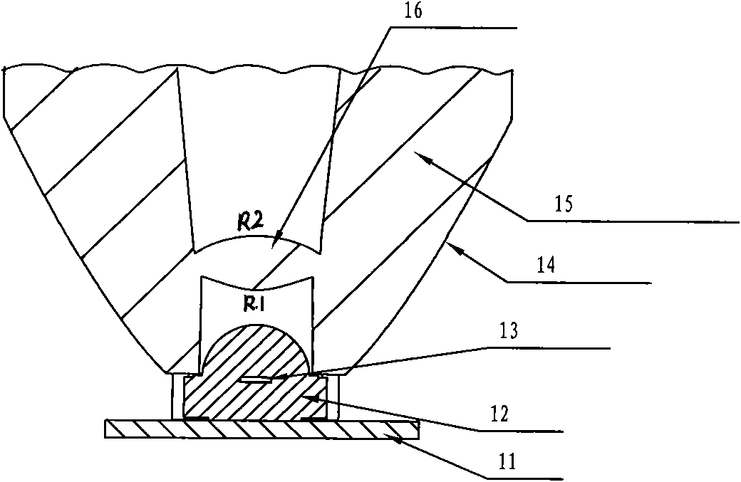
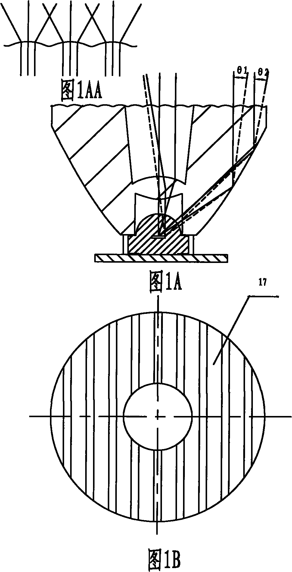
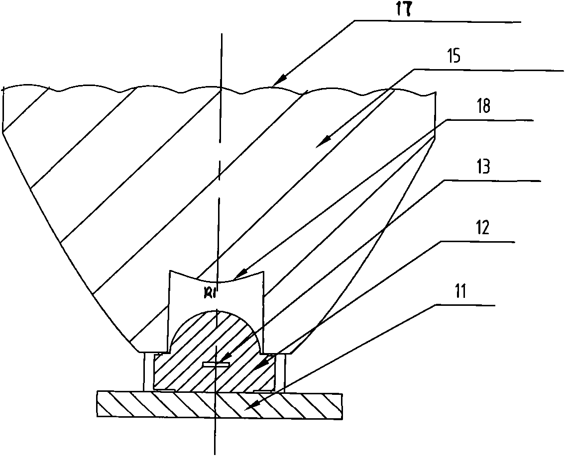
[0043] see figure 1 and Figure 1A, this light-emitting unit is a B-type lamp cup, which is composed of a lens-type lamp cup 15, LED lamp beads 12 and a circuit board 11 (a circuit board is equipped with multiple lens-type lamp cups and LED lamp beads to form multiple light unit). The lamp cup is injection-molded with PMMA optical material with a light transmittance of over 92.8%, and is a solid lens. The side surface 14 of the lamp cup is a parabolic reflective surface formed by turning a parabola along the axial direction of the lamp cup (of course, it can also be a spherical reflective surface formed by a section of circular arc turning along the axial direction of the lamp cup). An LED lamp bead installation hole is left in the center of the cup holder...


PUM


Abstract

The invention provides an LED luminescent unit and a motorcycle LED headlamp light source thereby. The LED luminescent unit consists of a lens type lamp cup, an LED bulb and a circuit board, wherein the focus of a parabolic reflecting surface or a spherical reflecting surface of the lamp cup is superposed with the focus of a double-face convex lens or a single-face convex lens, the superposed focus is positioned between the real focus and the virtual focus of the emergent light of the LED bulb or is positioned in the real focus or the virtual focus. The top of the lamp cup is a plane or at least a vertically arranged cylindrical surface is distributed on the top of the lamp cup. In the invention, the structure of the lamp cup and the installation position of the bulb in the lamp cup are reasonably designed, thereby both the emergent light brightness of the luminescent unit and molding facula can achieve ideal effects. When the LED luminescent unit is used as the light source of an LED headlamp, the effects of reducing power, improving illumination and prolonging service life without emitting heat are achieved, and the potential safety hazard can be eliminated.

Description

technical field [0001] The invention belongs to the LED light source technology, and in particular relates to an LED light emitting unit and a light source with the effect of high beam or low beam. Background technique [0002] LED (Light Emitting Diode) is known as the fourth-generation light source, which has the advantages of long life, high luminous efficiency, and no radiation. The theoretical life of LED is more than 100,000 hours, and the luminous efficiency is as high as 90%, while the energy consumption of the same luminous flux is only 8% of that of incandescent lamps, which has the obvious advantages of being green and low-carbon. LEDs have been widely used in the field of lighting all over the world. [0003] At present, motorcycle headlamps (front combination lamps) mainly use incandescent filament lamps and halogen lamps as light sources, and reflect the light in front of the motorcycle through the reflection of reflective bowls. Due to the low luminous effic...

Claims


Application Information

Patent Timeline
Patent Type & Authority Applications(China)
IPC IPC(8): F21S8/10F21V13/04F21V19/00B62J6/02F21W101/10F21Y101/02
Inventor 代天荣黄益华李易
Owner 重庆科鹰电气有限公司
Learn More