D shape guide pin top and bottom positioning structure of hole position check tool

A technology of hole position degree and positioning structure, applied in the direction of measuring device, using mechanical device, mechanical measuring device, etc., can solve the problems of difficult to reach, unable to stay at a certain height, and inconvenient to use the inspection tool, and to improve The effect of convenience

Active Publication Date: 2010-10-13
ROYAL GAUGE IND
View PDF1 Cites 9 Cited by
  • Summary
  • Abstract
  • Description
  • Claims
  • Application Information

AI Technical Summary

Problems solved by technology

In the process of designing and manufacturing product inspection tools, when the holes of the inspection products are square or special-shaped holes, in order to facilitate alignment, the detection pins are generally designed to prevent rotation. However, such inspection tools are not very convenient to use in actual inspections. Sometimes The detection p

Method used


Image

  • D shape guide pin top and bottom positioning structure of hole position check tool
  • D shape guide pin top and bottom positioning structure of hole position check tool
  • D shape guide pin top and bottom positioning structure of hole position check tool

Examples


Embodiment Construction

[0013] The present invention will be specifically introduced below in conjunction with the accompanying drawings and specific embodiments.

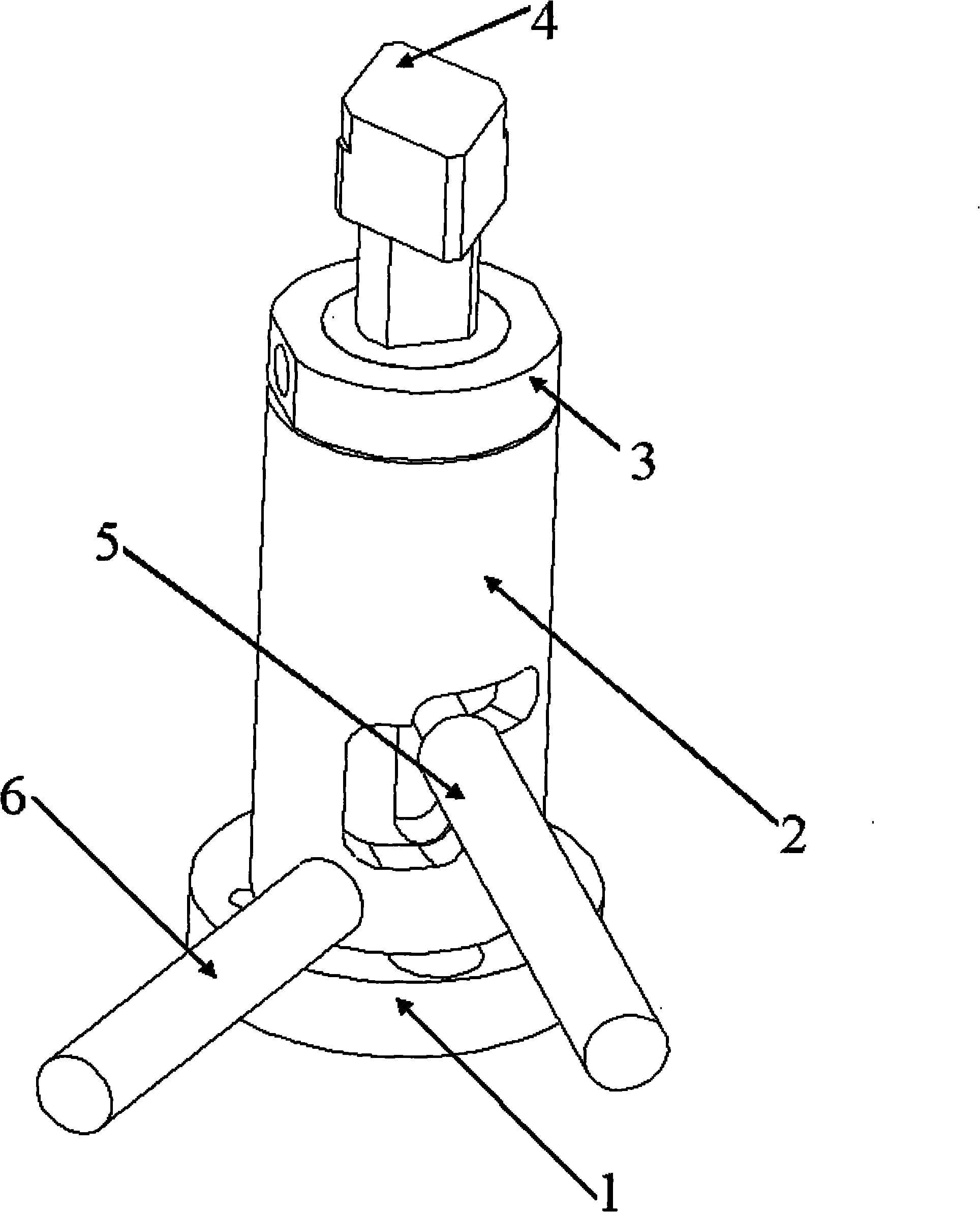
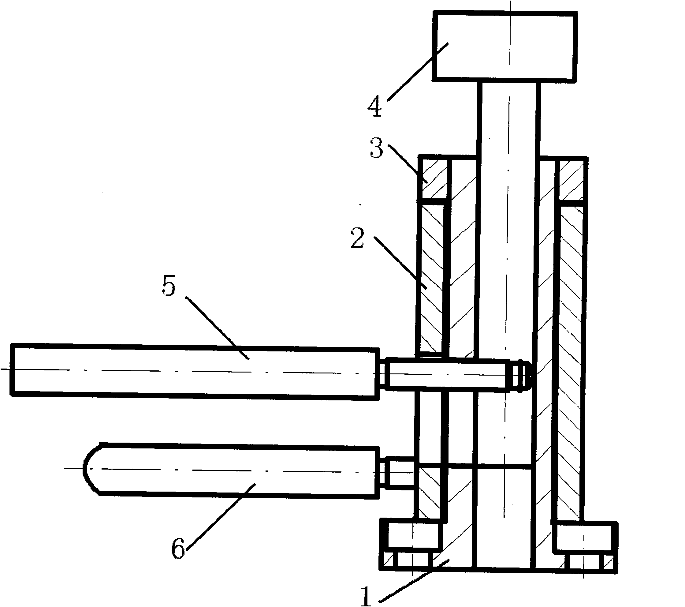
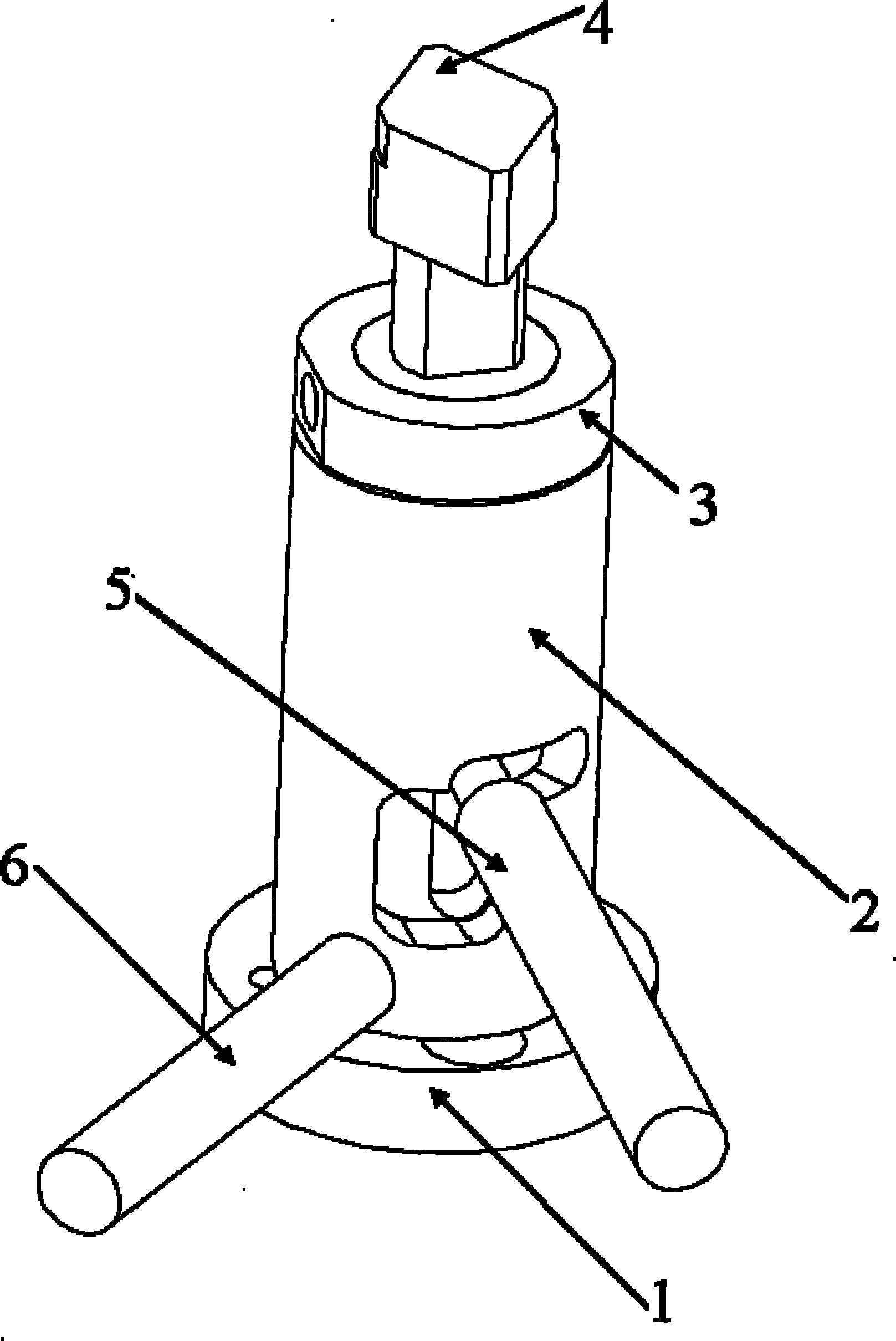
[0014] figure 1 It is a perspective view of the up and down positioning structure of the D-shaped guide pin of the hole position gauge of the present invention; figure 2 It is a sectional view of the present invention.

[0015] The upper and lower positioning structure of the D-shaped guide pin of the hole position inspection tool of the present invention includes a detection pin 4, a rotating sleeve 2, a D-shaped guide pin sliding bracket 1, a limit pressure block 3, an up and down toggle pin 5 and a rotary handle pin 6 Etc., the middle of the D-shaped guide pin sliding support 1 is hollow, and is sleeved on the outside of the detection pin 4, and the detection pin 4 can move up and down in the D-shaped guide pin sliding support 1 endoporus. A step surface with a larger diameter is provided on the lower end surface of the D-shaped gui...


PUM


Abstract

The invention relates to a D shape guide pin top and bottom positioning structure of hole position check tool, comprising a detection pin, a rotating sleeve and a D shape guide pin sliding support; wherein the D shape guide pin sliding support is sheathed at the outer side of the detection pin, the lower end face thereof is provided with a larger-diameter step face with a bolt hole; the rotating sleeve is sheathed at the outer side of the D shape guide pin sliding support, the upper side of the rotating sleeve is provided with a limit press cake; the outer side of the rotating sleeve is fixed with a rotating handle pin, the wall of the rotating sleeve is provided with an inversed 'L' shape first through hole, the wall of the D shape guide pin sliding support is provided with a vertical second through hole, one end of an up-down shifting pin is respectively fixed on the detection pin by virtue of the through holes on the rotating sleeve and the D shape guide pin sliding support. In the invention, the rotating sleeve is sheathed at the outer side of the D shape guide pin sliding support, so that the previous detection pin which only can move up and down and can not be fixed at certain position can be fixed at one specific position, thus improving convenience of operation.

Description

technical field [0001] The invention relates to a checking tool in mechanical processing, in particular to a D-shaped guide pin upper and lower positioning structure of the hole position checking tool for detecting the position degree of a product square or special-shaped hole on the checking tool. Background technique [0002] There will be many holes on the products we process, and the position accuracy requirements are relatively high, especially for some high-precision products, the position accuracy requirements of the holes are higher. Therefore, after the product is produced and before leaving the factory, it is necessary to use the inspection tool to detect its position. In the process of designing and manufacturing product inspection tools, when the holes of the inspection products are square or special-shaped holes, in order to facilitate alignment, the detection pins are generally designed to prevent rotation. However, such inspection tools are not very convenient...

Claims


Application Information

Patent Timeline
IPC IPC(8): G01B5/00
Inventor 董力郑锦春
Owner ROYAL GAUGE IND
Why Eureka
Try Eureka