Three-wheel inspection robot mechanism capable of crossing over catenary of pole and tower

An inspection robot and leap rod technology, which is applied in the directions of manipulators, overhead line/cable equipment, manufacturing tools, etc., can solve the problem of not mentioning inspection robot leaping and so on.

Inactive Publication Date: 2010-10-13
SOUTH CHINA UNIV OF TECH
View PDF10 Cites 30 Cited by
  • Summary
  • Abstract
  • Description
  • Claims
  • Application Information

AI Technical Summary

Problems solved by technology

Patent ZL200410010531.5 and patent ZL200610045435.2 respectively introduced a wheel-arm compound type and a wheel-claw compound type i...

Method used


Image

  • Three-wheel inspection robot mechanism capable of crossing over catenary of pole and tower
  • Three-wheel inspection robot mechanism capable of crossing over catenary of pole and tower
  • Three-wheel inspection robot mechanism capable of crossing over catenary of pole and tower

Examples


Embodiment 1

[0044] Embodiment 1 straddles the anti-vibration hammer

[0045] Anti-vibration hammer is a very common obstacle on power lines. Figure 2a to Figure 2h It shows the whole movement process of the inspection robot across the anti-vibration hammer.

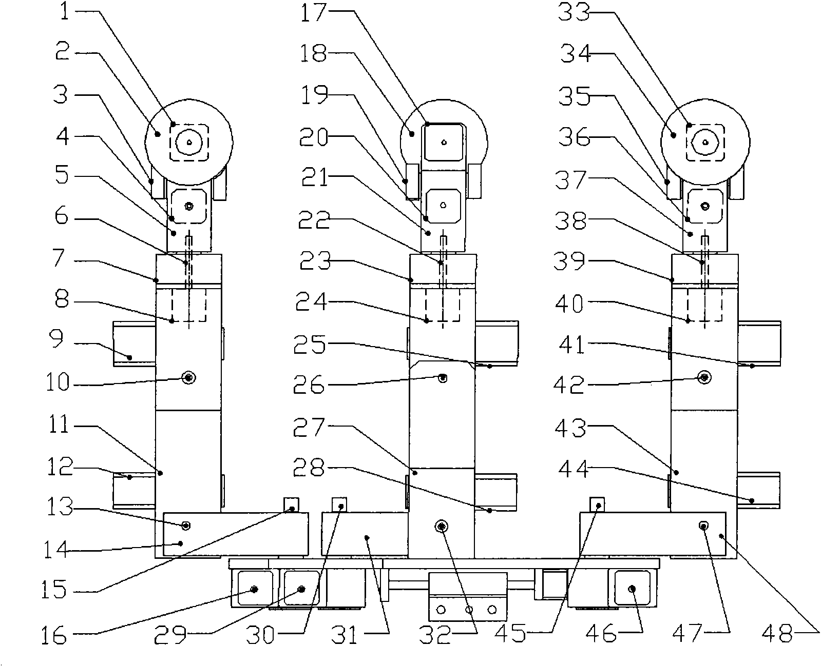
[0046] first step, such as Figure 2a As shown, when the inspection robot moves to the front of the anti-vibration hammer, it first stops moving. At this time, the middle arm (11, 27, 43) and upper arm (7, 23, 39) of the forearm group, middle arm group and rear arm group 1, wrists (5, 21, 37) are all in a vertical state, and are on a vertical line, and respectively maintain a vertical state with the lower arm (14, 31, 48). The handwheels (2, 18, 34) of the three arm groups are all on the power line. Three clamp hands (3,19,35) are in unclamped state.

[0047] The second step, such as Figure 2b As shown, the front hand wheel 2 of the forearm group is offline. Now, the middle arm 27 rotates counterclockwise with respect to the ...

Embodiment 2

[0054] Embodiment 2 Drainage conductor across the tower

[0055] first step, such as Figure 3a As shown, when the front hand wheel of the inspection robot arrives at the junction of the drain wire 59 and the power line 60 and stops moving, the middle arm (11, 27, 43), upper arm (7, 23, 39), wrist ( 5, 21, 37) are all in a vertical state, and on a vertical line, and maintain a vertical state with the lower arm (14, 31, 48). The hand wheels ( 2 , 18 , 34 ) of the three arm groups are all on the power line 60 . The three hands (3, 20, 35) are released.

[0056] The second step, such as Figure 3b As shown, the middle middle arm 27 of the middle arm group rotates counterclockwise with respect to the middle lower arm 31, and the middle upper arm 23 of the middle arm group rotates clockwise with respect to the middle middle arm 27 at the same speed. Meanwhile, the rear middle arm 43 of the rear arm group rotates clockwise with respect to the rear lower arm 48, and the rear uppe...


PUM


Abstract

The invention discloses a three-wheel inspection robot mechanism capable of crossing over the catenary of a pole and tower, which comprises a three arm groups; each arm group is installed on a base respectively through a gear box and respectively provided with two rotational degrees of freedom in a horizontal plane, two rotational degrees of freedom in a vertical plane and one rolling degree of freedom, and a front hand clamp is respectively installed on the wrist via each arm group, which can prevent the robot from dropping out from a power line; and a gravity center adjusting and balancing mechanism is arranged below the base, which can freely slide in front of, behind and on left and right of the robot body, and a robot electrical device connected below the gravity center adjusting and balancing mechanism is taken as a balancing block, so that the arm group which moves away can newly return to the power line after finishing the planning actions. By adopting the structure, the robot can stably run on the power line and also can cross over the obstacles on the power line, such as wire clips, vibration dampers and the like, and more importantly, the robot can smoothly cross over the drainage wire.

Description

technical field [0001] The invention relates to a mobile robot mechanism, in particular to a three-wheel inspection robot mechanism capable of crossing a tower suspension line. Background technique [0002] Regular fault detection and repair of high-voltage overhead transmission lines is the basic guarantee of power supply reliability. Because the overhead line is in the field environment, it is exposed to wind and rain for a long time, and it is affected by continuous mechanical tension, electrical flashing, and material aging, which is easy to cause wear, broken strands, corrosion and other damage. If it is not repaired and replaced in time, it is easy to cause damage. Serious accidents cause large-scale power outages and economic and property losses. At present, there are mainly two methods for inspection of power transmission lines: the ground eye-to-eye method and the helicopter aerial survey method. The manual maintenance method of the ground visual inspection method...

Claims


Application Information

Patent Timeline
IPC IPC(8): H02G1/02B25J5/00B25J18/00B25J19/00
Inventor 田联房王孝洪毛宗源
Owner SOUTH CHINA UNIV OF TECH
Why Eureka
Try Eureka