Stator core with winding for medium-sized low-voltage variable-frequency motor

A frequency conversion motor and stator core technology, applied in windings, electric components, manufacturing of motor generators, etc., can solve the problems of increasing the capacity of the frequency converter, easy collision of paint films, short-circuit faults between turns, etc., to improve dv/dt value, good insulation performance between turns, and the effect of improving power factor

Inactive Publication Date: 2010-10-13
WUXI ZHONGDA MOTORS
View PDF0 Cites 9 Cited by
  • Summary
  • Abstract
  • Description
  • Claims
  • Application Information

AI Technical Summary

Problems solved by technology

In recent years, domestic high-power frequency conversion motors mostly adopt stacked or concentric windings with loose wires. Due to the high power of the motor, low voltage, large current, high inter-turn working voltage, and loose enamelled round copper wires, due to their Existing pinholes and defects caused by the manufacturing process (such as damage to the paint film during the manufacturing process of winding, off-line, etc., the quality of the dipping paint) and the first turn and the last turn of the coil scattered in the slot are easy to collide, and run for a period of time. Turn-to-turn short-circuit faults often occur after a period of time, which reduces the reliability of medium-sized low-voltage variable-frequency motors and shortens the life of medium-sized low-voltage variable-frequency motors
If open slots and formed windings are used, the power factor of the motor is not high, the iron loss is large, and the efficiency is low, which increases the capacity of the inverter

Method used


Image

  • Stator core with winding for medium-sized low-voltage variable-frequency motor
  • Stator core with winding for medium-sized low-voltage variable-frequency motor
  • Stator core with winding for medium-sized low-voltage variable-frequency motor

Examples


Embodiment Construction

[0013] The present invention will be further described below in conjunction with specific drawings and embodiments.

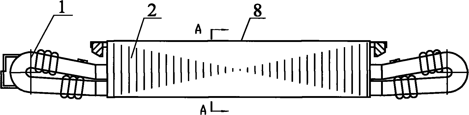
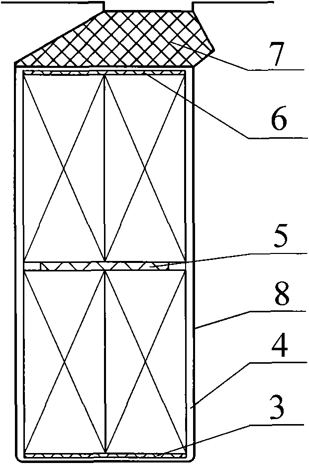
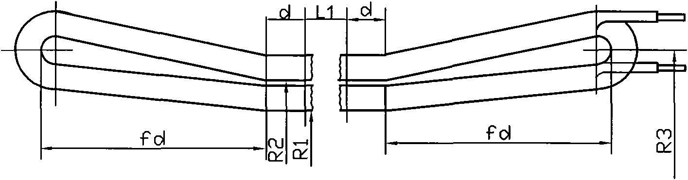
[0014] As shown in the figure: the present invention is mainly composed of semi-formed winding 1, semi-open slot stator punching sheet 2, bottom pad 3, slot body insulation layer 4, middle pad 5, adjustment pad 6, slot wedge 7 and installation slot body 8, etc. .

[0015] The medium-sized low-voltage frequency conversion motor has a winding stator core, including semi-formed winding 1, half-open slot stator punching plate 2, bottom pad 3, slot body insulation layer 4, middle pad 5, adjustment pad 6, slot wedge 7 and installation slot body 8. The semi-formed winding 1 is installed at both ends of the installation tank 8, the top of the installation tank 8 is open, and the installation tank 8 is provided with a tank insulation layer 4 that matches the shape of the cavity. In the tank insulation layer 4 Place the bottom pad 3 on the bottom layer of the cavity, pl...


PUM


Abstract

The invention relates to a stator core with a winding for a medium-sized low-voltage variable-frequency motor, which comprises semi-formed windings, semi-open slot stator punched plates, a bottom pad, a slot insulation layer, a middle pad, a regulation pad, a slot wedge and a mounting slot, wherein the semi-formed windings are arranged at the two ends of the mounting slot; the slot insulation layer is arranged in the mounting slot; the bottom pad is placed on the bottom layer of the inner cavity of the slot insulation layer; a lower-layer stator coil formed by the semi-open slot stator punched plates is placed on the bottom pad; the middle pad is placed on the lower-layer stator coil; an upper-layer stator coil formed by the semi-open slot punched plates is placed on the middle pad; the regulation pad is placed on the upper-layer stator coil; the slot wedge is placed on the regulation pad; and the upper-layer and lower-layer coils are connected with the circuit of the semi-formed windings. The stator core improves the power factor and efficiency of the motor, reduces the capacity of the transducer, has high inter-turn insulation performance and improves the dv / dt value of the motor easily, thereby improving the reliability of the medium-sized variable-frequency motor.

Description

technical field [0001] The invention relates to a winding stator core of a medium-sized low-voltage high-power variable-frequency motor, in particular to a winding stator core of a low-voltage high-power variable-frequency motor with a center height of 315-710 mm. Background technique [0002] With the rapid development of the domestic electric power industry and the application of high-efficiency variable-frequency speed-regulating transmission systems more and more widely, it is more urgent to develop low-voltage high-power variable-frequency speed-regulating three-phase asynchronous motors. Generally, variable frequency motors are powered by transistor inverters. Transistor inverters use high-frequency pulses, and the pulse rise and fall time is very short. How to ensure that the winding insulation does not break down under the peak value of pulse voltage has become the key to the reliability of variable frequency motors. In recent years, domestic high-power frequency con...

Claims


Application Information

Patent Timeline
Patent Type & Authority Applications(China)
IPC IPC(8): H02K1/16H02K3/38H02K15/085H02K3/48
Inventor 张高峰刘丰玮范乐平张亚平
Owner WUXI ZHONGDA MOTORS
Why Eureka
Try Eureka