Low-noise rotor chamber for a centrifuge

一种离心机转子、转子腔的技术,应用在离心机领域,能够解决离心机噪声高、恼人等问题

Active Publication Date: 2010-10-20
QIAGEN GMBH
View PDF7 Cites 5 Cited by
  • Summary
  • Abstract
  • Description
  • Claims
  • Application Information

AI Technical Summary

Problems solved by technology

[0005] However, it has been shown that despite the aforementioned measures, the noise produced by the centrifuge is still relatively high and still annoying

Method used


Image

  • Low-noise rotor chamber for a centrifuge
  • Low-noise rotor chamber for a centrifuge

Examples


Embodiment Construction

[0035] In the illustrated embodiment, the same parts are provided with the same reference signs hereinafter.

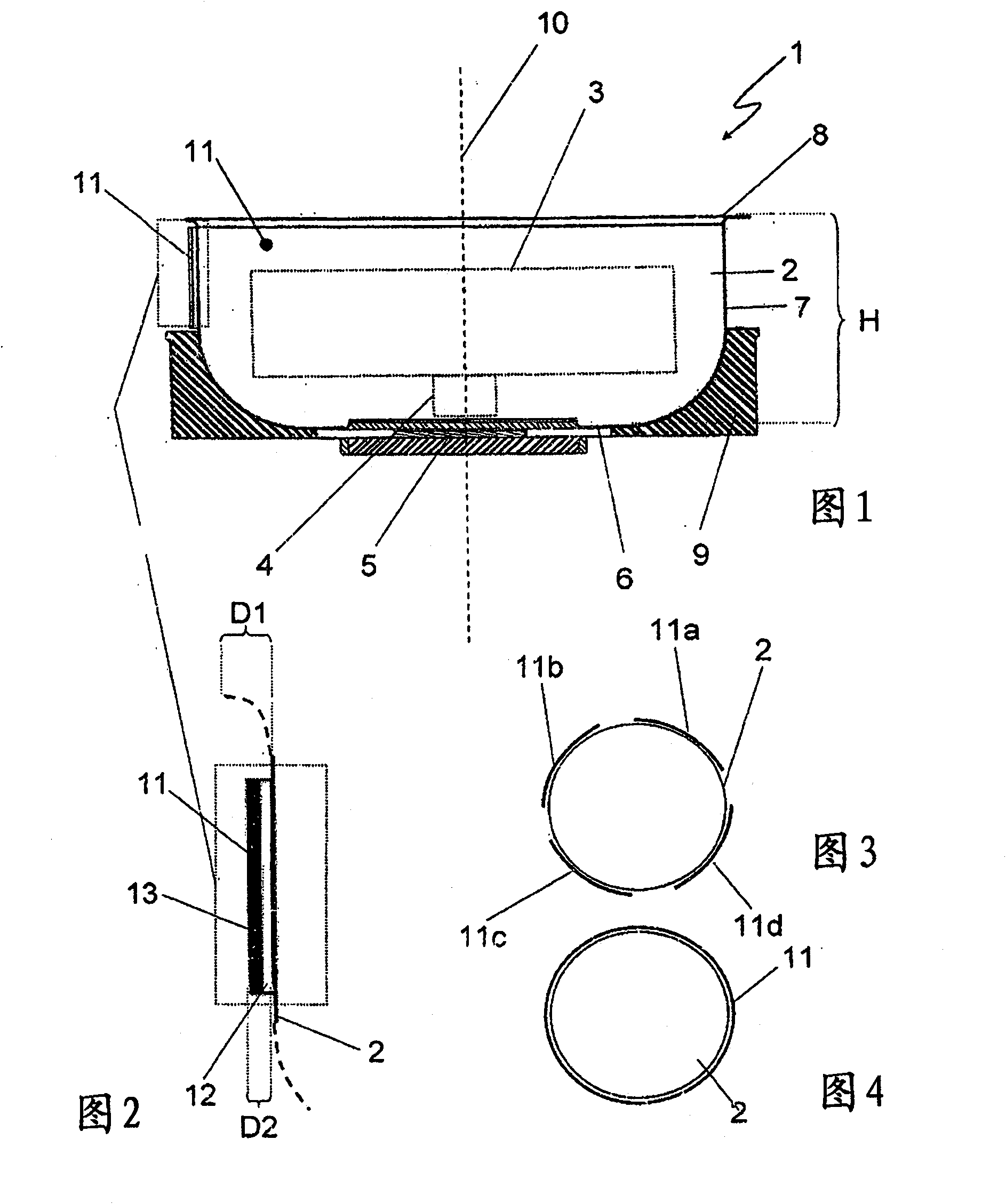
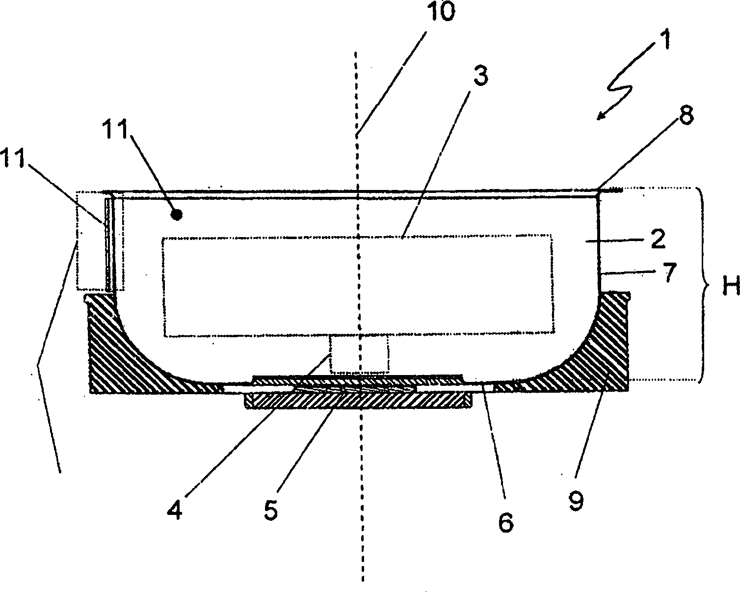
[0036] exist figure 1 The centrifuge 1 is only partially shown in the figure, which comprises a rotor chamber 2 in a housing (not shown), the rotor chamber 2 is provided with a rotor chamber interior 2a for receiving a rotor 3 (in particular a pair of oscillating Outer rotor), the rotor 3 is connected to the motor element 5 via a drive shaft 4 . The rotor chamber 2 also comprises a flat base area 6 , a wall area 7 adjoining on top of the base area and an upper edge area 8 . The rotor chamber 2 is designed to be open at the top, and the outside is covered by a cover (not shown) during operation. Furthermore, in the lower region, the rotor chamber 2 is accommodated in a groove-shaped foam molding 9 which protrudes from the base region 6 by up to half the height H of the rotor chamber 2 . The damping lining 11 adjoins the top of the foam-molded part 9 in the direction...


PUM


Abstract

The present invention relates to a rotor chamber for a centrifuge, in particular an air-cooled laboratory centrifuge, having a chamber wall, comprising an inner side facing toward the chamber interior, the chamber interior being implemented to receive a centrifuge rotor, and an outer side facing away from the chamber interior, and having a sound barrier which is implemented to reduce the sound emitted from the rotor chamber, which comprises a multilayer damping lining. The present invention also relates to a centrifuge having such a rotor chamber, and methods for reducing the sound emanating from the rotor chamber of a centrifuge, in particular an air-cooled laboratory centrifuge.

Description

technical field [0001] The invention relates to a rotor chamber for a centrifuge, in particular an air-cooled laboratory centrifuge, having a chamber wall comprising: an inner side facing the interior of the chamber for receiving the centrifuge rotor; and an outer side facing away from the interior of the cavity, which has a sound barrier for attenuating the sound emitted by the rotor cavity. Furthermore, the invention relates to a centrifuge having such a rotor chamber and a method for damping the sound emitted by the rotor chamber of a centrifuge, in particular of an air-cooled laboratory centrifuge. Background technique [0002] Centrifuges, especially air-cooled laboratory centrifuges, often produce a noticeable background noise, sometimes very noticeable during operation, which can be found annoying to those nearby. There are many causes for this sometimes noticeable background noise during centrifuge operation. Thus, for example, even a slight unbalanced weight of th...

Claims


Application Information

Patent Timeline
Patent Type & Authority Applications(China)
IPC IPC(8): B04B7/02
CPCB04B7/02B04B15/02
Inventor H·扬岑
Owner QIAGEN GMBH
Why Eureka
Try Eureka