
Glue spreader

A technology of gluing machine and gluing roller, which is applied in the field of gluing machines, can solve the problems of large amount of glue used, increase of production cost, difficulty in guaranteeing the quality of pasting of the surface layer, etc., and achieve the goal of reducing production cost and reducing the amount of glue used Effect

Active Publication Date: 2012-11-21
WUXI SHENGJIN MACHINERY
View PDF0 Cites 3 Cited by
  • Summary
  • Abstract
  • Description
  • Claims
  • Application Information

AI Technical Summary

Problems solved by technology

[0002] In the production of composite flooring, it is necessary to glue the veneer on the surface of the base material, or to coat various types of synthetic leather, artificial paper or PVC on the surface of the wood board, and it is necessary to coat the surface of the wood board or the base material with glue. , the existing gluing machine usually includes a conveying back-up roller horizontally arranged on the frame and a gluing roller and a metering roller above it, when the substrate passes between the conveying backing roller and the gluing roller, the gluing roller Apply a layer of glue on the surface of the substrate, and the amount of glue applied is determined by the distance between the glue roller and the metering roller. When applying glue, the glue roller will apply the glue attached to the surface of the glue roller to the substrate During the process of attaching the material, due to the fluidity of the glue, the glue coated on the surface of the substrate is uneven, and the amount of glue used is large, which increases the production cost, and it is difficult to guarantee the quality of the surface layer.

Method used


Image

  • Glue spreader
  • Glue spreader
  • Glue spreader

Examples


Embodiment Construction

[0019] The specific implementation manners of the present invention will be further described in detail below in conjunction with the accompanying drawings.

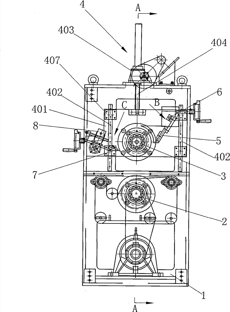
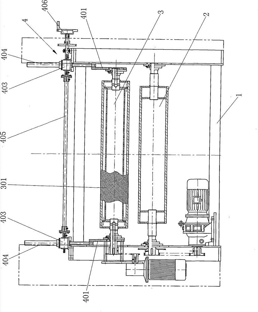
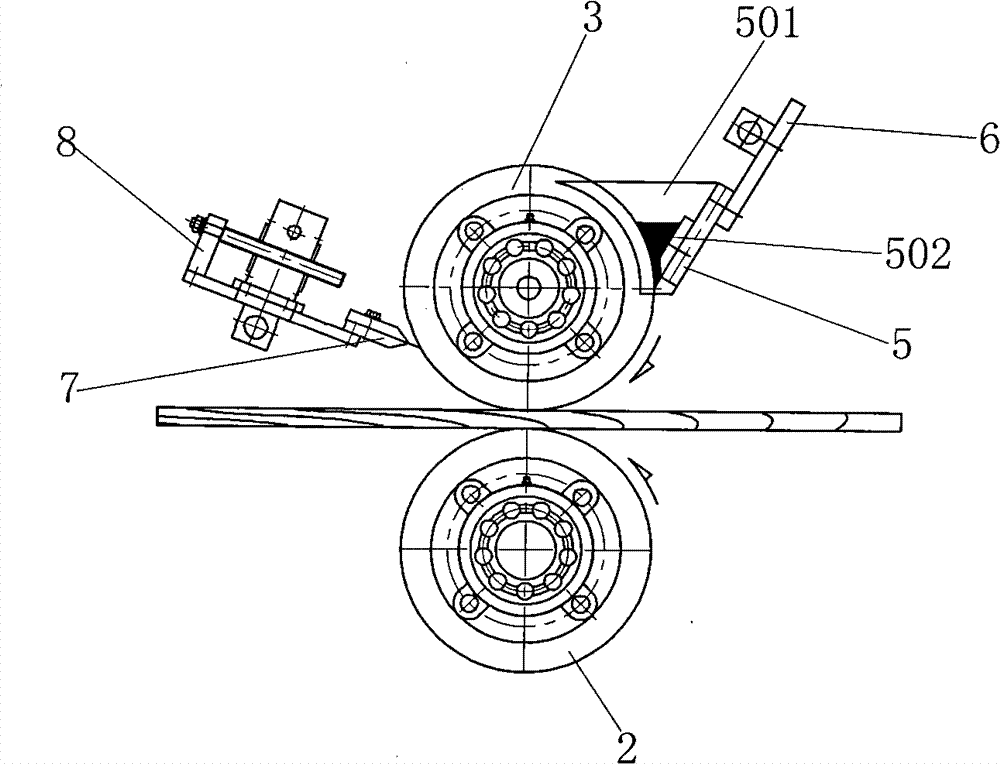
[0020] like figure 1 , 2 , 3, the present invention comprises a frame 1, the two ends of the conveying backup roller 2 are mounted on the frame 1 through bearings, the glue-coating roller 3 is arranged on the top of the conveying backup roller 2, the conveying backup roller 2 and the glue-coating roller 3 The driving mechanism is respectively connected, and the conveying backup roller 2 and the glue roller 3 are driven to rotate by the driving mechanism. The two ends of the glue roller 3 are installed on the lifting mechanism 4, and the lifting mechanism 4 is installed on the frame 1. Lifting mechanism 4 comprises the lifting wall panel 401 on both sides of frame 1 and the slide rail 402 that is installed on the frame, and lifting wall panel 401 is slidably installed on the slide rail 402 by slide block 407, and the fi...


PUM


Abstract

The invention relates to a glue spreader, which comprises a rack. The two ends of a conveying support roller are arranged on the rack. A glue spreading roller is arranged above the conveying support roller. The conveying support roller and the glue spreading roller are respectively connected with a driving mechanism. The invention is characterized in that the two ends of the glue spreading rollerare arranged on a lifting mechanism which is arranged on the rack, the surface of the glue spreading roller is provided with hatching knurling, one side of the glue spreading roller is provided with a measurement scraper which is connected with a measurement adjusting mechanism and the measurement adjusting mechanism is arranged on the lifting mechanism. The surface of the glue spreading roller is provided with the hatching knurling. Proper glue volume can be controlled and glue can be spread on the surface of base material evenly. When the surface course pasting quality is ensured, the glue usage amount and the manufacture cost are reduced.

Description

technical field [0001] The invention relates to a gluing equipment, in particular to a gluing machine for coating glue on the surface of a substrate. Background technique [0002] In the production of composite flooring, it is necessary to glue the veneer on the surface of the base material, or to coat various types of synthetic leather, artificial paper or PVC on the surface of the wood board, and it is necessary to coat the surface of the wood board or the base material with glue. , the existing gluing machine usually includes a conveying back-up roller horizontally arranged on the frame and a gluing roller and a metering roller above it, when the substrate passes between the conveying backing roller and the gluing roller, the gluing roller Apply a layer of glue on the surface of the substrate, and the amount of glue applied is determined by the distance between the glue roller and the metering roller. When applying glue, the glue roller will apply the glue attached to the...

Claims


Application Information

Patent Timeline
Patent Type & Authority Patents(China)
IPC IPC(8): B05C1/12B05C11/00
Inventor 盛金
Owner WUXI SHENGJIN MACHINERY
Learn More