Elbow pipe piece forming machine

A technology for forming machines and pipe fittings, applied in the field of elbow pipe fittings forming machines, can solve the problems affecting the appearance, strength, and troublesome operation of bending pipe fittings.

Inactive Publication Date: 2010-10-20
何崇翔
View PDF0 Cites 9 Cited by
  • Summary
  • Abstract
  • Description
  • Claims
  • Application Information

AI Technical Summary

Problems solved by technology

Due to the different sizes of the pipe fittings, when the relatively small pipe fittings are bent, there will be a relatively small gap between the pipe fittings and the bending mold. During the bending process, there will be more wrinkles on the bent pipe fittings, which not only affects the to the appearance of the bent pipe, and its strength will also be affected
[0003] In order to solve such p

Method used


Image

  • Elbow pipe piece forming machine
  • Elbow pipe piece forming machine
  • Elbow pipe piece forming machine

Examples


Embodiment Construction

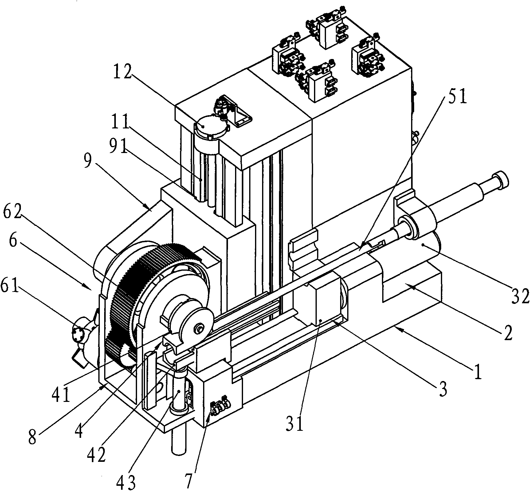
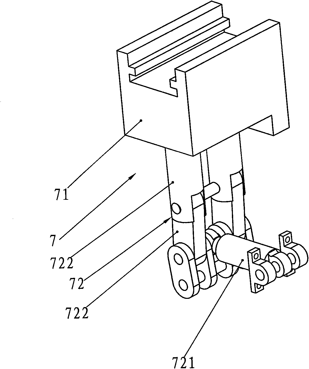
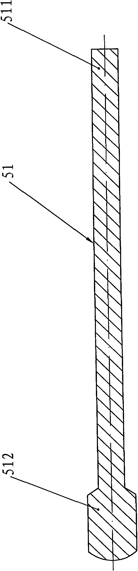
[0016] Such as Figure 1-Figure 3 The shown elbow pipe fitting forming machine includes a body 1, a workbench 2 arranged on the body 1, a pusher mechanism 3 arranged on the workbench 2, a bending mechanism 4 connected with the pusher mechanism 3, a core The rod 51, the mandrel positioning mechanism 5 and the driving mechanism 6 for driving the bending mechanism 4; The propulsion cylinder 32 that slides along the workbench; the bending mechanism 4 includes a bending die 41 and a die clamping block 42 corresponding to the bending die 41, and the end face of the bending die 41 opposite to the die clamping block 42 is the The arc-shaped clamping groove 43 adapted to the surface, the mold clamp block 42 and the bending mold 41 rotate synchronously, the mandrel 51 includes a sleeve end 511 and an expansion end 512, and the diameter of the expansion end 512 of the mandrel 51 is larger than the sleeve end. 511, its sleeve end 511 is an end that conflicts with the mandrel positioning ...


PUM


Abstract

The invention relates to a forming machine, in particular to an elbow pipe piece forming machine. The technical scheme provided by the invention is as follows: the elbow pipe piece forming machine comprises a machine body, a working platform, a pipe-pushing mechanism, a bending mechanism, a core rod, a core rod positioning mechanism and a drive mechanism, wherein the bending mechanism comprises a bending mold and a mold clamping block arranged correspondingly to the bending mold; the end surface of the bending mold, which is opposite to the mold clamping block, is an arc-shaped clamping groove which is matched with the peripheral surface of a pipe piece; the mold clamping block and the bending mold rotate synchronously; the core rod comprises a sheathing end and an expanding end; the diameter of the expanding end of the core rod is larger than that of the sheathing end which is the end butted with the core rod positioning mechanism; the expanding end is the end between the bending mold and the mold clamping block; and the mold clamping block position is provided with a mold locking mechanism which achieves mold combination or separation of the mold clamping block and the bending mold. By adopting the technical scheme, the invention provides the elbow pipe piece forming machine which has convenient operation and can not lead the bent pipe piece to generate wrinkles.

Description

technical field [0001] The invention relates to a forming machine, in particular to an elbow pipe fitting forming machine. Background technique [0002] At present, the forming machinery used for forming elbow pipe fittings is widely used in the market and materials. This type of machinery mainly consists of a machine base, a workbench on the machine base, a pusher mechanism on the workbench, and a pusher mechanism. The connected bending mechanism, mandrel, mandrel positioning mechanism and driving mechanism for driving the bending mechanism, the push tube mechanism includes a push tube seat which is arranged on the worktable and slides laterally along the workbench, and drives the push tube seat to work along the The propulsion cylinder of the table slides; the bending mechanism includes a bending die and a die clamping block corresponding to the bending die, and the end surface of the bending die opposite to the die clamping block is an arc-shaped clamping groove adapted t...

Claims


Application Information

Patent Timeline
IPC IPC(8): B21D9/00
Inventor 何崇翔
Owner 何崇翔
Why Eureka
Try Eureka