Method for forming diameter-variable parts by viscoelastic-plastic flexible die

A reduction ratio, viscoelastic technology, applied in the field of sheet metal forming, can solve the problems of unstable forming, wrinkling, etc., and achieve the effect of low manufacturing cost, low pressure and promoting flow

Active Publication Date: 2012-03-14
HARBIN INST OF TECH
View PDF1 Cites 0 Cited by
  • Summary
  • Abstract
  • Description
  • Claims
  • Application Information

AI Technical Summary

Problems solved by technology

[0005] The purpose of the present invention is to solve the problem that the existing forming method is only suitable for the variable diameter parts with a small reducing ratio per unit length, and the wrinkling phenomenon is easy to occur during the forming process, resulting in unstable forming, and then provides a large reducing ratio. Viscoelastic-plastic Soft Molding Method for Variable Diameter Parts

Method used


Image

  • Method for forming diameter-variable parts by viscoelastic-plastic flexible die
  • Method for forming diameter-variable parts by viscoelastic-plastic flexible die
  • Method for forming diameter-variable parts by viscoelastic-plastic flexible die

Examples


specific Embodiment approach 1

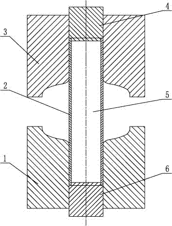
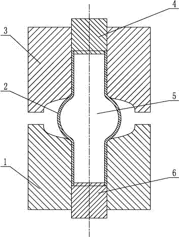
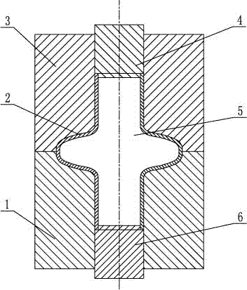
[0016] Specific implementation mode one: combine Figure 1-Figure 3 To illustrate this embodiment, the steps of a viscoelastic-plastic soft mold forming method for a variable diameter part with a large diameter reduction ratio in this embodiment are as follows:

[0017] Step 1: install the upper end of the tube blank 2 in the cavity of the upper mold 3, install the lower end of the tube blank 2 in the cavity of the lower mold 1, and simultaneously use the lower plunger 6 to seal the lower end of the tube blank 2;

[0018] Step 2: filling the inside of the shell 2 with the viscoelastic plastic material 5;

[0019] Step 3: Use the upper plunger 4 to seal the upper end of the tube blank 2, and press the lower end of the upper plunger 4 into the tube blank 2 to compact the viscoelastic-plastic material 5 to form a pre-pressure of 1-3 MPa;

[0020] Step 4: Install and position the upper die 3 and the lower die 1 on the press, and determine the gap between the upper die 3 and the l...

specific Embodiment approach 2

[0025] Embodiment 2: This embodiment differs from Embodiment 1 in that: the wall thickness of the tube blank 2 is 1 mm to 4 mm. The formed variable diameter parts have higher dimensional accuracy.

specific Embodiment approach 3

[0026] Embodiment 3: The difference between this embodiment and Embodiment 1 or 2 is that the viscoelastic plastic material 5 in step 2 has a molecular weight of 400000g / mol~600000g / mol and a viscosity of 10000Pa·s~16000Pa·s. The state of matter of the molecular polymer material and the viscoelastic plastic material 5 is semi-solid. The viscoelastic-plastic material 5 has better strain rate sensitivity, is more adaptable to stress changes during the deformation process of the shell 2, and better suppresses possible wrinkling during the forming process.


PUM

PropertyMeasurementUnit
viscosityaaaaaaaaaa
thicknessaaaaaaaaaa

Abstract

The invention relates to a method for forming a diameter-variable part viscoelastic-plastic flexible die with large variable diameter ratio, in particular to a method for forming diameter-variable part flexible die. The invention solves the problems that the existing forming method is only applicable to diameter-variable parts having small variable-diameter ratio per unit length, the quality control is difficult, the dimensional accuracy of the formed diameter-variable parts is low and the manufacturing cost thereof is high. The method of the invention comprises the following steps: mounting a tube blank in the cavity of a die; sealing the lower end of the tube blank by using a lower plunger; filling the tube blank with viscoelastic-plastic materials; sealing the upper end of the tube blank by using an upper plunger, and pressing the lower end of the upper plunger in the tube blank to compact the viscoelastic-plastic materials, thus forming the pre-pressure; mounting the die on a press; closing the die, and attaching the tube blank to the cavity of the die under the pressure of the viscoelastic-plastic materials inside the cavity and the pressure of the upper die and the lower die to form the parts; opening the die and taking out the formed parts along with the viscoelastic-plastic materials therein as a whole; and removing the viscoelastic-plastic materials inside the formed parts. Accordingly, the method of the invention is applicable for forming diameter-variable parts.

Description

technical field [0001] The invention relates to a method for forming soft molds of parts with variable diameters, and belongs to the technical field of plate forming. Background technique [0002] The shell part with a large diameter change per unit length is a typical part widely used in the fields of aviation, aerospace and automobiles. The current main forming method for this type of part is separate forming and then combined welding. The dimensional accuracy of the part is affected by the The impact of each separate forming process makes quality control difficult, and the existence of welds seriously affects the quality and performance of parts and increases manufacturing costs. As the requirements for dimensional accuracy, surface quality and manufacturing efficiency of variable diameter parts are getting higher and higher, the existing forming methods can no longer adapt; and the current forming methods cannot meet other one-time forming technologies (such as spinning ...

Claims


Application Information

Patent Timeline
Patent Type & Authority Patents(China)
IPC IPC(8): B21D22/10
Inventor 王忠金宋辉胡泊李继光
Owner HARBIN INST OF TECH
Why Eureka
Try Eureka