Deep hole processing equipment

A processing equipment and deep hole technology, applied in metal processing equipment, turning equipment, turning equipment, etc., can solve the problems of affecting production efficiency, affecting processing accuracy, high manufacturing cost, etc., achieve low manufacturing cost and use cost, and improve processing accuracy and efficiency, protection of health and safety

Active Publication Date: 2012-01-11
MIANYANG BRILLIANCE RUIAN AUTOMOTIVE COMPONENTS
View PDF2 Cites 0 Cited by
  • Summary
  • Abstract
  • Description
  • Claims
  • Application Information

AI Technical Summary

Problems solved by technology

Both of the above two structures use the movement of the steady rest to clamp the workpiece, that is, the clamping position of the workpiece is fixed, and the positioning of the processing end face and the tool varies with different workpieces. Every time the workpiece is replaced, the initial processing position of the tool They must be re-determined, thereby affecting the machining accuracy and production efficiency, and they do not have a sealing effect. During cooling and chip removal, the rotation of the rotating part in the steady frame will cause non-directional splashing of dust and spatter, thus Pollution to the factory environment and threats to the safety and health of operators
[0005] When the tool is fed in the traditional deep hole processing equipment, the feed system adopts the ball screw nut pair transmission, driven by the servo motor, the manufacturing cost is high, and it lacks stability in the deep hole processing with high processing quality requirements. It is easy to affect the processing quality of deep holes, and when problems such as high hardness of the workpiece material and tool wear occur during processing, the machine tool cannot automatically respond to adjust the amount of cutting

Method used


Image

  • Deep hole processing equipment
  • Deep hole processing equipment
  • Deep hole processing equipment

Examples


Embodiment Construction

[0022] The present invention will be further described below in conjunction with accompanying drawing.

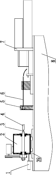
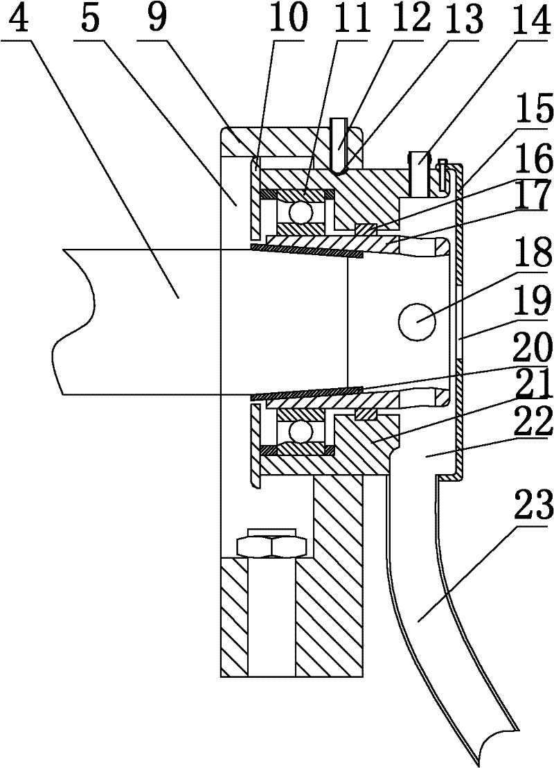
[0023] Such as figure 1 , figure 2 As shown, the present invention includes a bed body 8, a feed system 7, a center frame 5, a cutting tool 6 and a spindle box 2, the feed system 7 and the center frame 5 are installed on the bed body 8, and the tool 6 is arranged on the feed system 7 , the bed body 8 is provided with a linear guide rail 39, the spindle box 2 is installed on the linear guide rail 39 and is axially displaced through the linear guide rail 19, the spindle box 2 is provided with a tapered top 3, and the center frame 5 is provided with a 5. The workpiece top tight sleeve 20 with moving fit, the inner wall of the workpiece top tight sleeve 20 is conical, and the conical top 3 is coaxial with the workpiece top tight sleeve 20. The spindle box 2 can be slidably matched with the linear guide rail 39 through a chute, and can also be rolled with the linear guide rai...


PUM


Abstract

The invention discloses processing equipment, in particular to deep hole processing equipment. The invention provides the deep hole processing equipment, which has the advantages of simple and convenient clamping and reliable positioning and comprises a bed body, a feed system, a center frame, a tool and a spindle box. The feed system and the center frame are arranged on the bed body. The tool isarranged on the feed system. The bed body is provided with a linear guide rail. The spindle box is arranged on the linear guide rail and carries out axial displacement by the linear guide rail. The spindle box is provided with a cone tip. The center frame is provided with a workpiece pressing sleeve in movable fit with the center frame. The inner wall of the workpiece pressing sleeve is of a coneshape. The cone tip is coaxial with the workpiece pressing sleeve. A workpiece is clamped between the cone tip and the center frame by the displacement of the spindle box. The deep hole processing equipment has the advantages of simple and convenient clamping operation and reliable positioning, also can provide convenience for the subsequent tool positioning and is favorable to the improvement ofthe processing accuracy and efficiency.

Description

technical field [0001] The invention relates to a processing device, in particular to a deep hole processing device. Background technique [0002] The so-called deep hole refers to the hole whose length is much larger than the diameter, such as some oil channel through holes, the length of the through hole is 400-500mm, the size of the hole is φ8mm, and the aspect ratio is more than 50, which is extremely difficult to process. The processing method can hardly complete the above processing. The conventional processing method uses a special machine tool and uses a gun drill to process in sections. The cost of the equipment itself is relatively high, and the processing cost is also relatively high. The average time required to process a product is 5- 10 minutes, its processing efficiency is also unsatisfactory. [0003] The main difficulties in deep hole machining are as follows: 1. The workpiece itself has a large length-to-diameter ratio, which makes installation and positio...

Claims


Application Information

Patent Timeline
Patent Type & Authority Patents(China)
IPC IPC(8): B23B5/00B23B23/00B23B25/04B23Q1/76B23Q5/26
Inventor 谢贤清马桂华庞巧琴舒万强
Owner MIANYANG BRILLIANCE RUIAN AUTOMOTIVE COMPONENTS
Why Eureka
Try Eureka