Polishing method of non-spherical surface optical parts

A technology of optical parts and aspheric surfaces, applied in the field of machinery, can solve the problems that hinder the popularization of aspheric parts processing and production, the quality of parts surface finishing is uncertain, and the real-time control of polishing force cannot be controlled, so as to achieve the benefit of hardware design and The effect of software development, improving the quality of finishing processing, and overcoming the problem of inaccurate force control

Inactive Publication Date: 2010-10-20
NINGBO UNIV
View PDF7 Cites 9 Cited by
  • Summary
  • Abstract
  • Description
  • Claims
  • Application Information

AI Technical Summary

Problems solved by technology

But utilize the above-mentioned equipment to process and have following technical defect: (1) because only by the position servo control of CNC machine tool cutting process, the part is processed in the processing process, and can't carry out real-time control to the lapping and polishing force acting on the part, thereby make The polishing force of the curved surface polishing process is uncertain and inconsistent, resulting in uncertain and inconsistent finishing quality of the part surface; (2) The cost of equipment is high. Generally, the value of each CNC machine tool is in the millions or even tens of millions, which is extremely high. Great hindrance to the popularization of production of aspheric parts processing

Method used


Image

  • Polishing method of non-spherical surface optical parts
  • Polishing method of non-spherical surface optical parts
  • Polishing method of non-spherical surface optical parts

Examples


Embodiment Construction

[0018] The present invention will be further described in detail below in conjunction with the accompanying drawings and embodiments.

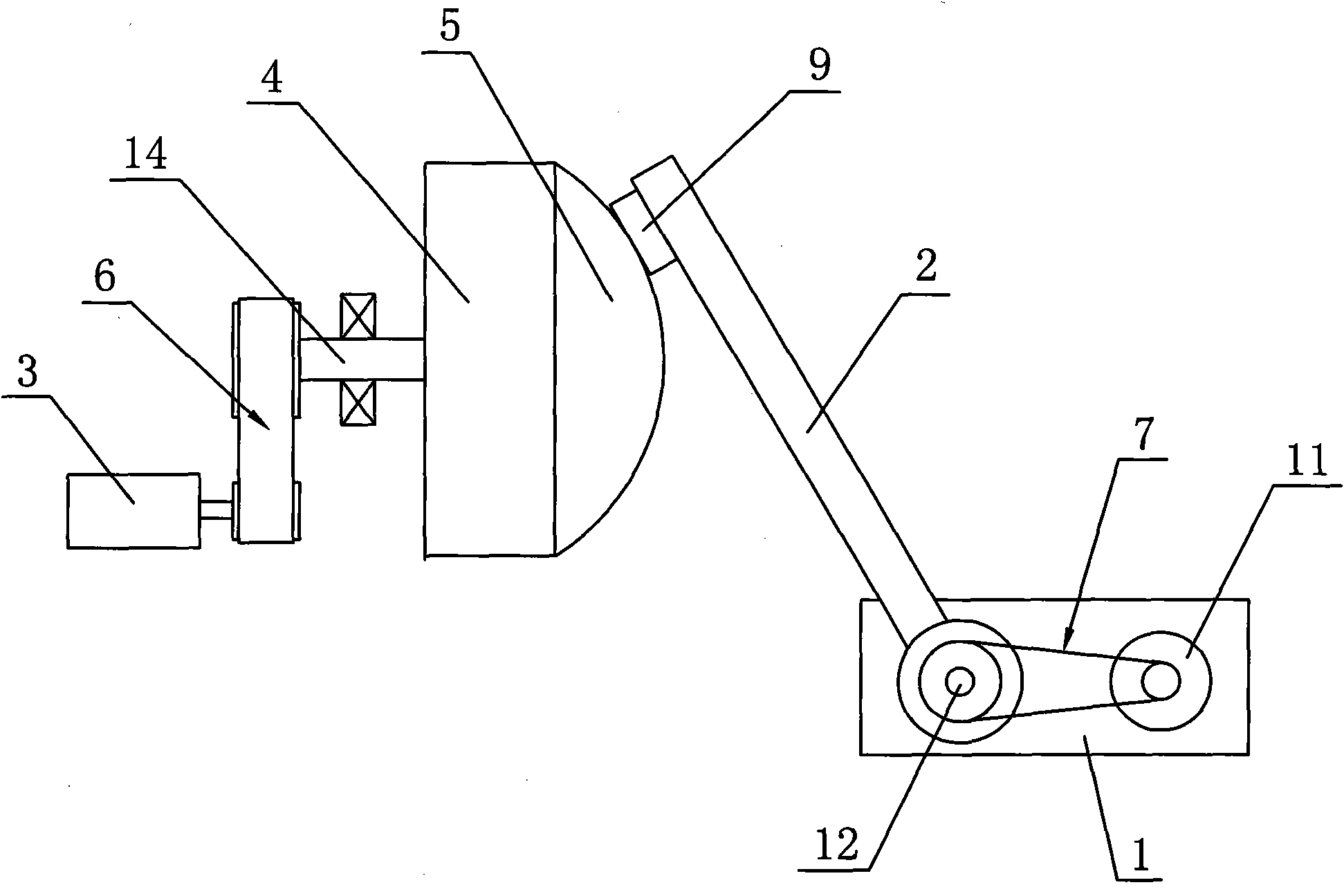
[0019] As shown in the figure, a method for polishing an aspheric optical part includes the following specific steps:

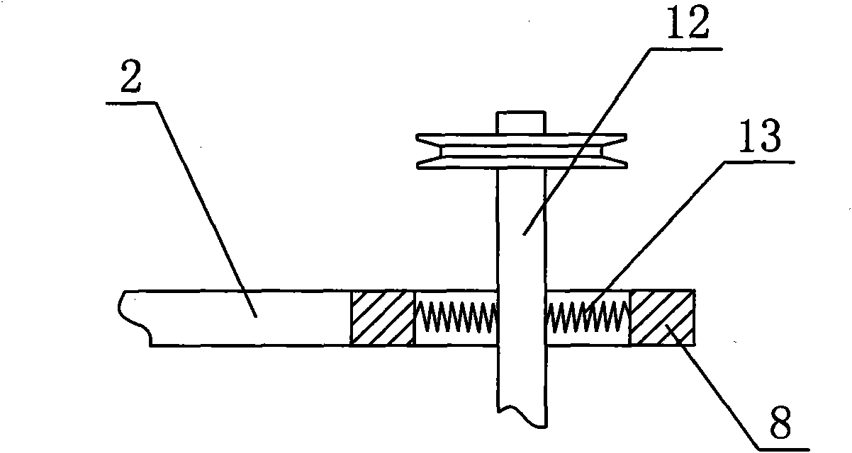
[0020] (1), the first motor 11 and the first transmission shaft 12 are installed on the servo workbench 1 in the CNC machine tool, and the first transmission mechanism 7 is connected on the first motor 11 to drive the first transmission shaft 12 to rotate, and then The turntable 8 is coaxially sleeved on the first transmission shaft 12, and a compliance control device composed of three evenly distributed springs 13 is connected between the turntable 8 and the first transmission shaft 12, and the turntable 8 is fixedly connected with one end of the rotating arm 2. , the other end of the rotating arm 2 is fixedly connected to the grinding tool 9;

[0021] (2), the second transmission mechanism 6 is connected on the second moto...


PUM


Abstract

The invention discloses a polishing method of non-spherical surface optical parts, which has the advantages that the polishing normal force can be directly controlled in the processing process by the polishing method, the problem of inaccurate force control caused by softening mechanical system force/position coupling problems can be solved, and the invention is favorable for obtaining stable and uniform curve surface outlines, and improves the part surface finishing processing quality. In addition, a softening control mode is adopted for processing the non-spherical surface optical parts, high requirements on the mechanical system precision of the precision finishing is avoided, the manufacture cost of equipment is reduced, and the invention is favorable for popularized application. In addition, the method of the invention has simple processing principle, and is favorable for hardware design and software development.

Description

technical field [0001] The invention relates to a method for processing parts in the mechanical field, in particular to a method for grinding and polishing aspheric optical parts. Background technique [0002] Aspherical optical parts have attracted extensive attention of researchers because of their good optical properties. In recent years, the research and development of aspheric optical parts polishing technology and equipment generally use ultra-precision multi-axis CNC machine tools as a platform, and process in the form of multi-axis CNC interpolation motion servo to realize the numerical control of the aspheric surface polishing process. Precision, to a certain extent, improves the processing efficiency of lapping and polishing. But utilize the above-mentioned equipment to process and have following technical defect: (1) because only through the position servo control of CNC machine tool cutting process, parts are processed in the processing process, and can't carry ...

Claims


Application Information

Patent Timeline
Patent Type & Authority Applications(China)
IPC IPC(8): B24B37/00B24B47/20
Inventor 詹建明郑堤胡利永
Owner NINGBO UNIV
Why Eureka
Try Eureka