Ejecting rod drawing device of large stamping die

A technology for taking out devices and stamping dies, which is applied to hand-held tools, manufacturing tools, etc., can solve problems such as the influence of the strength and service life of the ejector rod, reduce the force area, and increase the cost of major revisions, so as to achieve a simple manufacturing process and shorten the manufacturing time. The effect of low cycle and maintenance cost

Active Publication Date: 2011-12-14
CHERY AUTOMOBILE CO LTD
View PDF0 Cites 0 Cited by
  • Summary
  • Abstract
  • Description
  • Claims
  • Application Information

AI Technical Summary

Problems solved by technology

[0006] Some manufacturers have improved the ejector rod structure by drilling holes in the head of the ejector rod, or adding threaded mechanisms, or adding other self-locking mechanisms, but the above improvements (or improvements) require reprocessing of the ejector rod, and Changed the head structure of the ejector pin to reduce the force-bearing area, requiring a lot of modification costs, which will affect the strength and service life of the ejector pin

Method used


Image

  • Ejecting rod drawing device of large stamping die
  • Ejecting rod drawing device of large stamping die
  • Ejecting rod drawing device of large stamping die

Examples


Embodiment Construction

[0025] Referring to the accompanying drawings, through the description of the embodiments, the specific implementation of the present invention, such as the shape, structure, mutual position and connection relationship between the various parts, the function and working principle of each part, and the manufacturing process And the method of operation and use, etc., are described in further detail to help those skilled in the art have a more complete, accurate and in-depth understanding of the inventive concept and technical solution of the present invention.

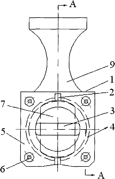
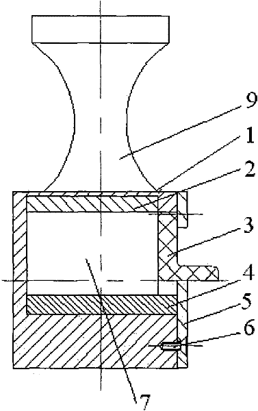
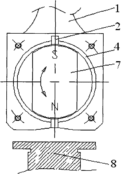
[0026] Such as Figure 1 to Figure 4 The structure of the present invention expressed is that the present invention is a ejector pin removal device for a large stamping die. When the workbench where the mold is installed leaves the stamping position of the stamping machine and the mold is suspended, the ejector pin 8 is taken out.

[0027] The problem to be solved by the present invention is that the ejector pin 8 can be...


PUM


Abstract

The invention discloses an ejecting rod drawing device of a large stamping die. When a working platform provided with a die is started to depart from a stamping position of a stamping machine tool and the die is put down, the ejecting rod (8) is drawn. The ejecting rod drawing device is characterized by having a rod-shaped structure; and the position adjacent to one end of the device is provided with a magnetic sucking structure, and the other end is provided with a handle (9). By adopting the technical scheme, after the working platform is started for the first time and the die is put down, the ejecting rod can be directly drawn by using the drawing device; the invention has the characteristics of simple manufacturing process, simple and convenient operation, long service life, low maintenance cost, and the like and can effectively shorten the manufacturing period of the die, prolong the use period of the die and save great time, labor and materials.

Description

technical field [0001] The invention belongs to the technical field of pressure manufacturing process equipment, and relates to a die structure technology for cold stamping processing, and more specifically, the invention relates to a ejector pin extracting device of a large stamping die. Background technique [0002] In modern automobile production, large cold dies are used to manufacture structural components. Among them, a large number of parts are formed by drawing, and this type of mold needs to use a ejector mechanism. For some equipment with low degree of automation, the replacement process of the ejector pin is as follows: [0003] The workbench (with mould) is opened → the mold is lifted → the workbench is moved in → the original ejector pin is ejected → the original ejector pin is taken out → the position of the ejector pin is replaced → the workbench is opened → the mold is hoisted → the workbench is moved in. [0004] During this process, the workbench needs to...

Claims


Application Information

Patent Timeline
Patent Type & Authority Patents(China)
IPC IPC(8): B25B27/14
Inventor 胡辉汪权
Owner CHERY AUTOMOBILE CO LTD
Why Eureka
Try Eureka