Smart satellite earth observation time window generating method based on space analytic geometry

A technology of spatial analytic geometry and time window, which is applied in the field of time window generation involving smart satellite earth observation, and can solve the problems of rough earth sphere and satellite modeling, inability to obtain STK data, and no consideration of smart satellites.

Inactive Publication Date: 2012-05-09
NAT UNIV OF DEFENSE TECH
View PDF0 Cites 0 Cited by
  • Summary
  • Abstract
  • Description
  • Claims
  • Application Information

AI Technical Summary

Problems solved by technology

[0006] The method model of STK simulation is complex, involving a lot of domain knowledge, and the construction of the scene requires complex parameter configuration
At the same time, STK is embargoed to our country, so the use of STK and how STK realizes the data generated by the time window cannot be obtained
[0007] In the approximate geometric relationship, due to the rough modeling of the earth sphere and satellites, the accuracy is difficult to meet the requirements
However, this method does not consider the situation that the smart satellite has pitch, and cannot be applied to the generation of the smart satellite's earth observation time window
[0008] At the same time, neither of the above two technologies for generating time windows has considered the situation of smart satellites with pitching capabilities, and there is no such technology in the prior art that realizes the generation of time windows for earth observation of satellites with high maneuverability such as smart satellites. Related reports

Method used


Image

  • Smart satellite earth observation time window generating method based on space analytic geometry
  • Smart satellite earth observation time window generating method based on space analytic geometry
  • Smart satellite earth observation time window generating method based on space analytic geometry

Examples


Embodiment Construction

[0049] The present invention will be further described in detail below in conjunction with specific embodiments and accompanying drawings.

[0050] Such as Figure 8 As shown, the present invention's smart satellite earth observation time window generation method based on spatial analytic geometry mainly includes the following six steps, wherein step 1 only needs to be performed once for the same same satellite, and step 2 is performed once for a time window generation , and the remaining steps are executed each time according to the number of sequences generated by the initialization result to determine the number of executions. The detailed flow process of the inventive method is:

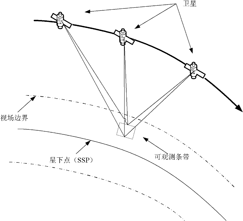
[0051] 1. Construct a spatial analytical geometric relationship model: The definition of sub-satellite points adopts the earth reference ellipsoid model, which is the intersection point of the connection line between the center of the earth and the satellite and the ellipsoid of the earth. The ...


PUM


Abstract

The invention relates to a smart satellite earth observation time window generating method based space analytic geometry, comprising the following six steps of: (1) establishing a space analytic geometry relational model, and using the model for carrying out coordinate transformation on the given substellar point and satellite coordinate; (2) initialization: pretreating the substellar point and target data, and forming substellar point target pair sequence; (3) angle inversion: carrying out angle inversion on each substellar point target in the substellar point target pair sequence, and obtaining a roll sequence and a pitch sequence corresponding to the substellar point target pair sequence; (4) rotation matrix inverse transformation: converting the roll sequence and the pitch sequence which are obtained in the step (3) into dynamic angle under a dynamic rotation coordinate system by inverse transformation; (5) obtaining smart satellite observation angle curve for observing the targetby calculation of interpolation; and (6) intercepting a time window. The smart satellite earth observation time window generating method has the advantages of simple and convenient operation, high accuracy, easy implementation and the like, and can be applied under the background of rotation with three degrees of freedom of a smart satellite.

Description

technical field [0001] The invention mainly relates to the field of satellite earth observation control, in particular to a method for generating a smart satellite earth observation time window. Background technique [0002] The mission of an Earth Observing Satellite (EOS) is usually to obtain image information of a designated target on the earth's surface according to the user's observation requirements. Because satellite observation has many advantages, it has been highly valued by countries all over the world. EOS usually implements observations according to a predetermined observation plan, which specifies when, what observation methods and observation tasks the satellite will perform, and its formulation is directly derived from the results of satellite observation scheduling. However, the traditional earth observation satellite push-broom imaging process completely depends on the forward movement of the satellite along the orbit, so the direction of the imaging strip...

Claims


Application Information

Patent Timeline
Patent Type & Authority Patents(China)
IPC IPC(8): G06F19/00
Inventor 贺仁杰姚锋邢立宁张正强
Owner NAT UNIV OF DEFENSE TECH
Why Eureka
Try Eureka