LED on-line detection control system
A technology for detecting control systems and control units, applied in instruments, static indicators, etc., can solve the problems of backward detection methods, low accuracy, and staying.
- Summary
- Abstract
- Description
- Claims
- Application Information
AI Technical Summary
Problems solved by technology
Method used
Image
Examples
Embodiment 1
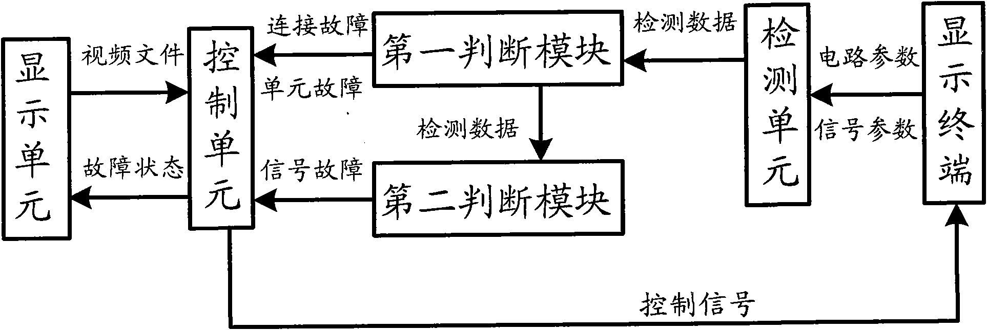
[0024] Such as figure 1 As shown, this embodiment provides an LED online detection control system, the LED online detection control system includes a display unit, a control unit, a detection unit and a judgment unit, wherein the LED online detection control system is used for online detection and Control each external display terminal. The display terminal includes various display devices, such as LED display screens, LED lighting, etc., and each display device can be used to display various graphics, text, letters, and animation videos. For example, it includes LED displays such as advertising screens, information screens, and animation video screens, and LED lighting such as underwater lights, guardrail tubes, and wall washers.
[0025] The control unit is connected to each component of the display terminal through a line, for example, is electrically connected to each component of the display terminal through a power line, and is signally connected to each control chip of ...
Embodiment 2
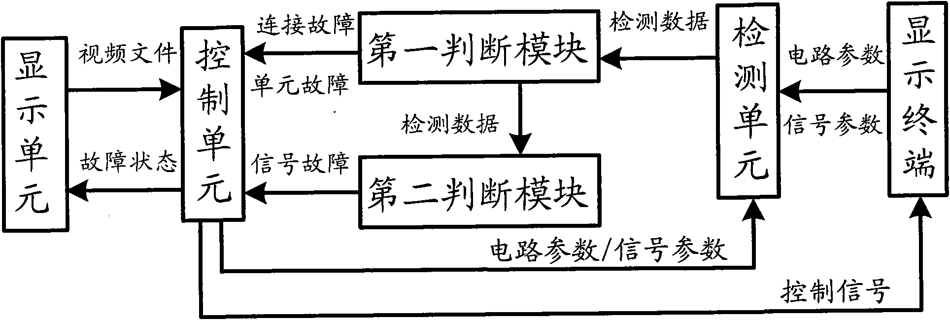
[0037] Such as figure 2 As shown, on the basis of the above examples, in the LED online detection control system provided by this embodiment, the detection unit is also connected to the control unit, the display unit, and the first judgment module, and the The detection unit is also used to detect the circuit parameters and signal input of the control unit, and generate detection data, and the first judging module judges whether the control unit is faulty, and if so, generates control unit fault data, and directly Outputting the control unit fault data to the display unit.
[0038] For example, the control unit fault data can be output to the display unit, and an alarm module can be set in the display unit, and when receiving the control unit fault data, an alarm signal is sent, such as, in the display unit By jumping out of the alarm window, in this way, it can be quickly known that the control unit is faulty, thereby avoiding wasting unnecessary resources.
[0039] Altern...
Embodiment 3
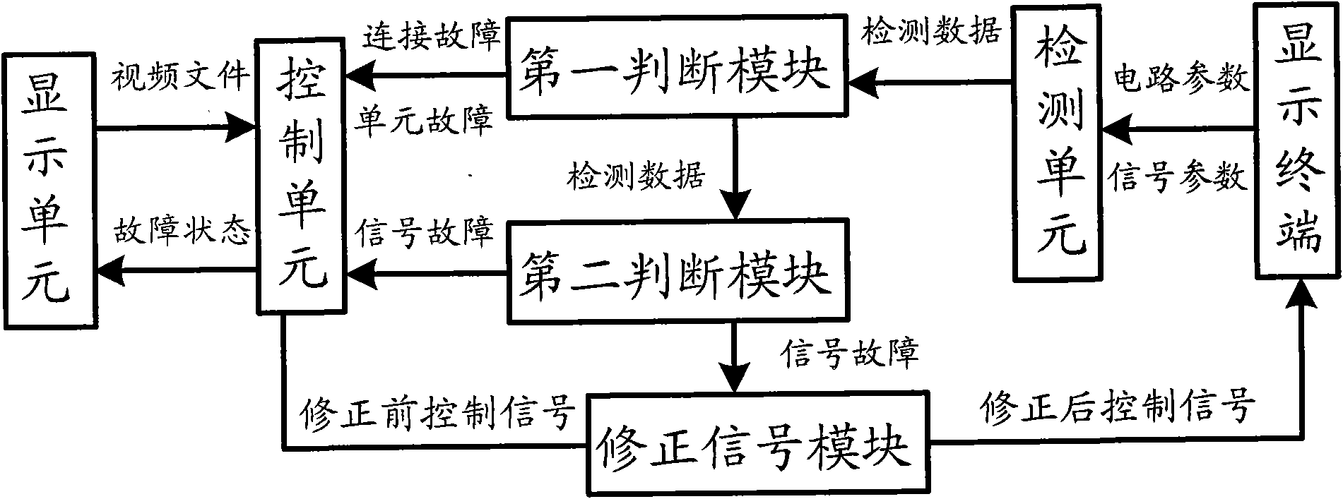
[0041] Such as image 3 As shown, on the basis of the above examples, in the LED online detection control system provided by this embodiment, the control unit is also provided with a signal correction module, and the signal correction module is respectively connected with the second judgment module and the connected to the control unit.
[0042] When the second judging module judges that a signal failure occurs in the display terminal, the signal correction module is started, and the signal correction module is configured to correct the control signal according to the second failure data.
[0043] For example, the control signal of each LED before correction is input into the signal correction unit, and the second judging module judges that the relevant components in the LED display terminal are signal faults according to the detection data, and then passes the second fault Data, the specific reason for the occurrence of the signal failure can be known, such as data loss, dat...
PUM
 Abstract
Description
Claims
Application Information
 - R&D
- Intellectual Property
- Life Sciences
- Materials
- Tech Scout
- Unparalleled Data Quality
- Higher Quality Content
- 60% Fewer Hallucinations
Browse by: Latest US Patents, China's latest patents, Technical Efficacy Thesaurus, Application Domain, Technology Topic, Popular Technical Reports.
© 2025 PatSnap. All rights reserved.Legal|Privacy policy|Modern Slavery Act Transparency Statement|Sitemap|About US| Contact US: help@patsnap.com


