Eureka AIR delivers breakthrough ideas for toughest innovation challenges, trusted by R&D personnel around the world.

Hologram device, tilt detection method, and tilt correction method

A technology for tilt detection and equipment, which is applied in the field of tilt correction for correcting tilt angles, which can solve the problems of deterioration of reproduction performance, offset, and drift of reproduced images, and achieves the effect of improving responsiveness.

Inactive Publication Date: 2010-10-20
SONY GRP CORP
View PDF5 Cites 10 Cited by
  • Summary
  • Abstract
  • Description
  • Claims
  • Application Information

AI Technical Summary

Problems solved by technology

[0013] Here, the holographic recording and reproducing system as described above has the problem that the reproducing performance is lowered due to the occurrence of the so-called tilt, which is usually the case with the existing optical disc systems such as CD (Compact Disc), DVD (Digital Versatile Disc) and the like.
[0014] In the case of holographic recording and reproduction systems, due to the occurrence of tilt, image drift of reproduced images occurs, resulting in deterioration of reproduction performance
[0015] In addition, if the tilt occurs, a shift may occur between the irradiation angle of the reference light when recording the hologram and the irradiation angle of the reference light when reproducing the hologram, and the reproduced image by diffraction cannot be properly obtained.
In this regard, it can also cause deterioration of the reproducibility

Method used


Image

  • Hologram device, tilt detection method, and tilt correction method
  • Hologram device, tilt detection method, and tilt correction method
  • Hologram device, tilt detection method, and tilt correction method

Examples


Embodiment Construction

[0059] Next, a configuration for realizing the present invention (hereinafter referred to as an embodiment) will be described. Description will be given in the following order.

[0060]

[0061]

[0062] [2-1. Behavior of light in an optical system]

[0063] [2-2. Generation principle of image drift due to tilt]

[0064]

[0065] [3-1. Generation of marker light]

[0066] [3-2. Tilt detection method]

[0067] [3-3. Tilt correction method]

[0068] [3-4. Construction to realize tilt detection method and tilt correction method]

[0069] [3-5. Outline of Embodiment]

[0070]

[0071]

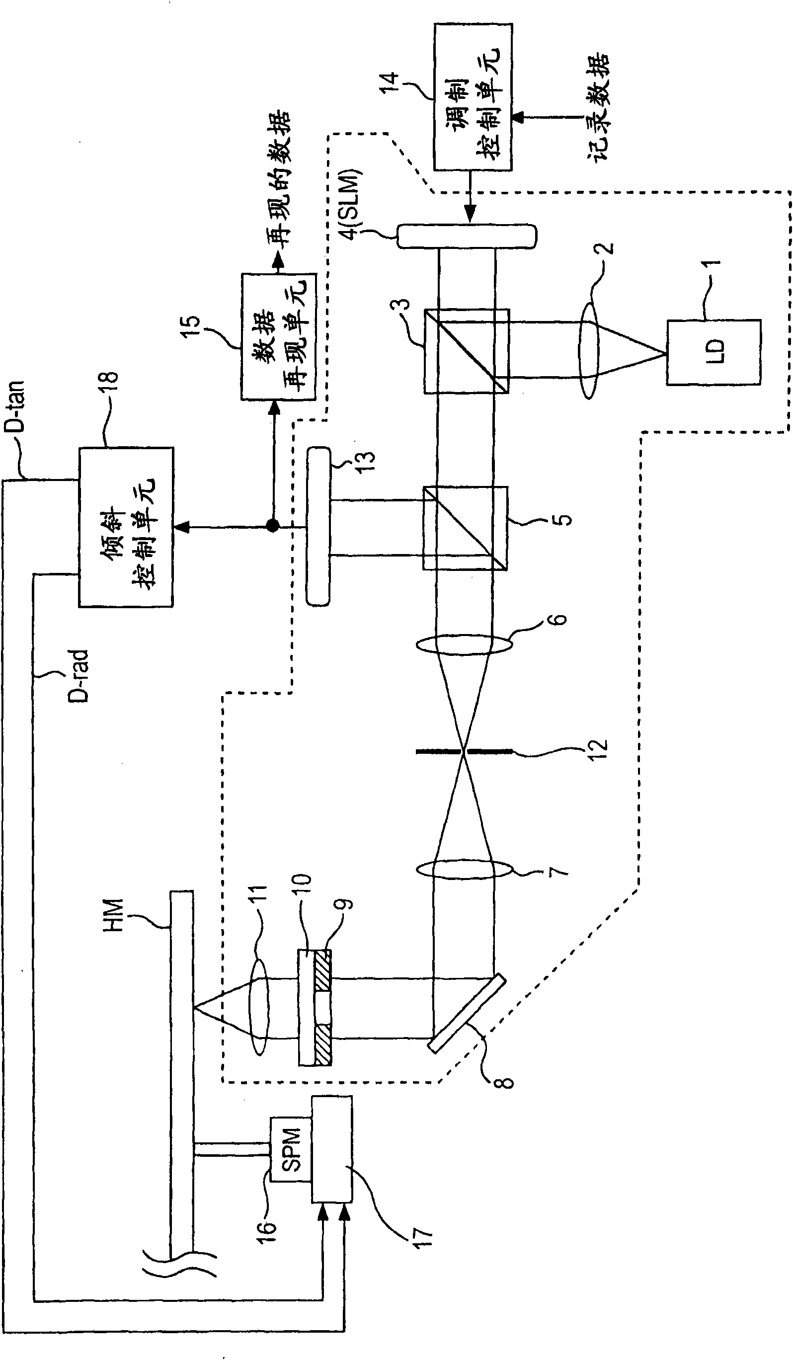
[0072] figure 1 The internal configuration of a recording and reproducing apparatus as an embodiment of a holographic apparatus according to an embodiment of the present invention is shown.

[0073] figure 1 The configuration of the optical system of the recording and reproducing apparatus of the embodiment is highlighted.

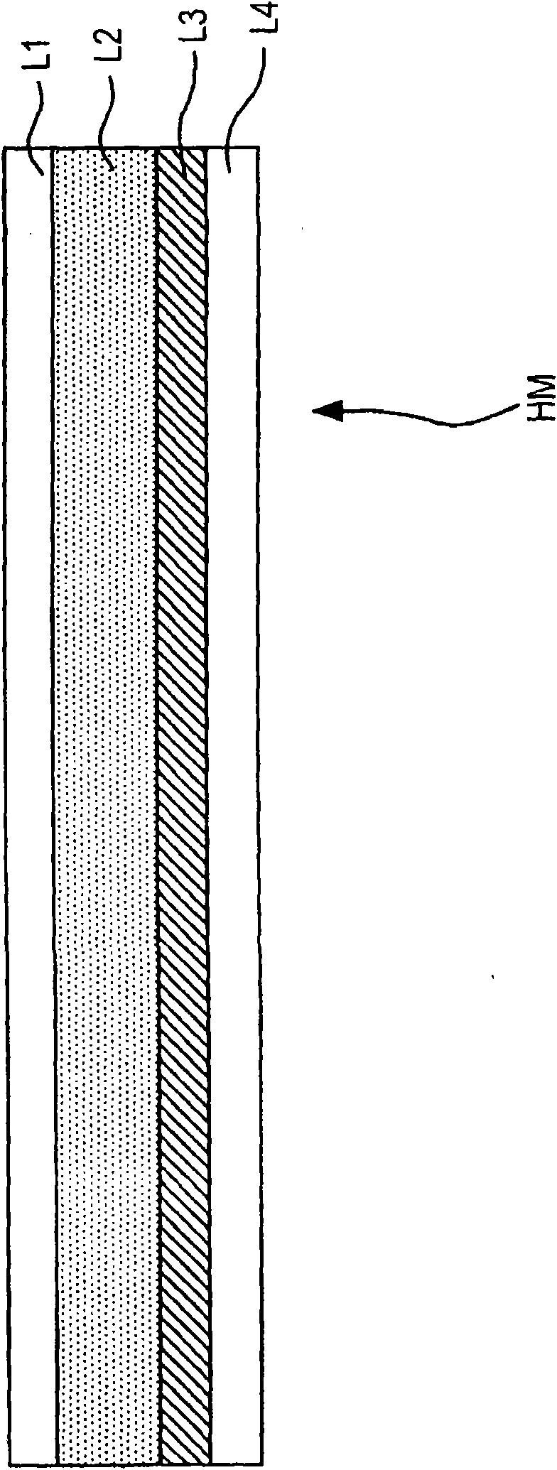
[0074] exist figure 1 Among them, the holographic r...


PUM

PropertyMeasurementUnit
wavelengthaaaaaaaaaa
angleaaaaaaaaaa

Abstract

The invention provides a hologram device, a tilt detection method, and a tilt correction method. The hologram device includes: a light source for applying light to a hologram recording medium having a recording layer in which information recording is performed by interference fringes between signal light and reference light; a spatial modulation unit that generates the signal light and / or the reference light and generates a marker light in a predetermined position within an incident surface of the light from the light source by performing spatial light modulation on the light from the light source; a light applying unit that applies the light subjected to spatial light modulation by the spatial light modulation unit to the hologram recording medium via an objective lens; a light receivingunit that receives the light applied via the objective lens through the hologram recording medium; and a tilt detection unit that obtains a tilt error signal representing an error from an ideal angleof a tilt angle as an incident angle of the applied light via the objective lens to an information recording surface of the hologram recording medium based on a result of detection of an error between an ideal light reception position of the marker light in the light receiving unit and a real light reception position of the marker light by the light receiving unit.

Description

technical field [0001] The present invention relates to a hologram device for recording and / or reproducing a hologram recording medium in which information is recorded using interference fringes between signal light and reference light. Further, the present invention relates to a tilt detection method for detecting a tilt angle which is an angle formed by an information recording surface of a hologram recording medium and an optical axis of light irradiated through an objective lens, and a tilt correction method for correcting the tilt angle. Background technique [0002] As disclosed in JP-A-2007-79438, there is known a hologram recording and reproducing method that performs data recording by forming a hologram. In this hologram recording and reproducing method, at the time of recording, signal light subjected to spatial light intensity modulation (intensity modulation) corresponding to recording data and reference light having a predetermined light intensity pattern (patte...

Claims


Application Information

Patent Timeline
Patent Type & Authority Applications(China)
IPC IPC(8): G11B7/0065G11B7/00
CPCG11B7/083G11B7/0956G11B7/0065
Inventor 山川明郎冈本好喜田中健二德山一龙高崎浩司
Owner SONY GRP CORP
Why Eureka
Eureka Blog
Learn More