Heat radiator

A technology for heat sinks and heat sinks, applied in indirect heat exchangers, lighting and heating equipment, electrical components, etc., can solve problems such as hindering heat transfer, limited thermal conductivity of heat-absorbing bottom plates, and reducing heat dissipation performance of heat sinks.

Inactive Publication Date: 2010-10-20
FURUI PRECISE COMPONENT (KUNSHAN) CO LTD +1
View PDF0 Cites 16 Cited by
  • Summary
  • Abstract
  • Description
  • Claims
  • Application Information

AI Technical Summary

Problems solved by technology

However, the thermal conductivity of the heat-absorbing base plate is limited, and there is thermal resistance between the heat pipe and the heat-absorbing base plate, which hinders heat transfer, thereby reducing the heat dissipation performance of the heat sink

Method used


Image

  • Heat radiator
  • Heat radiator
  • Heat radiator

Examples


Embodiment Construction

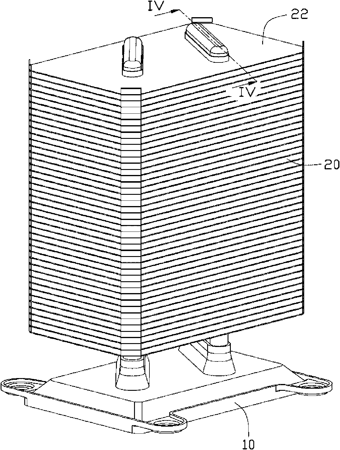
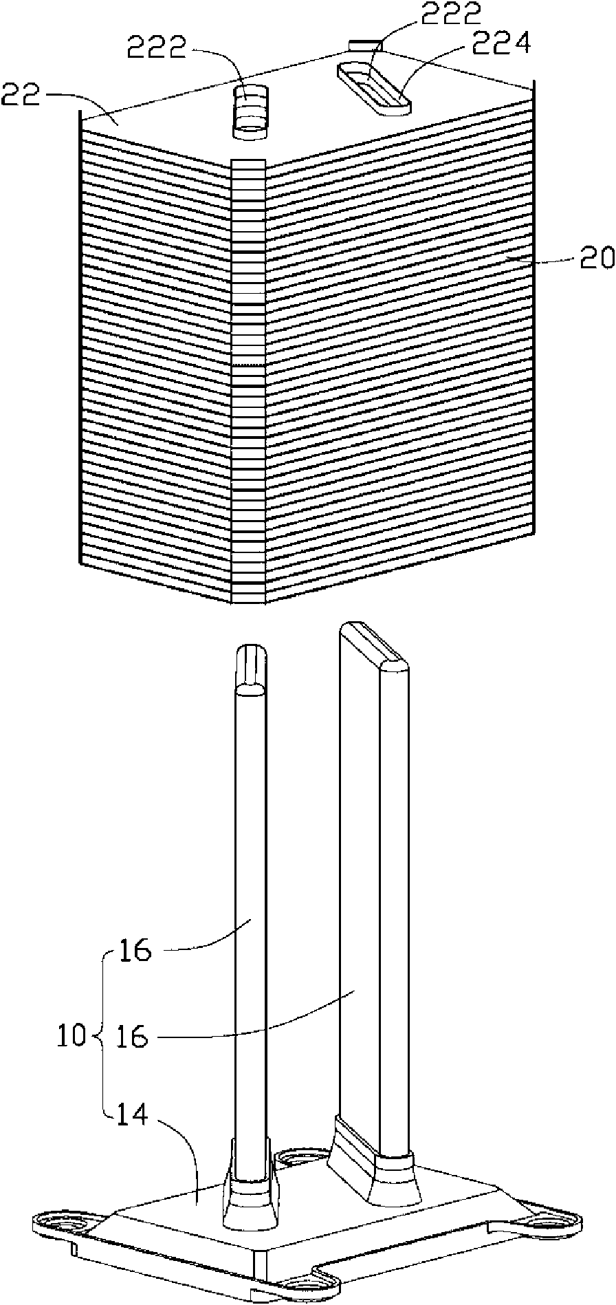
[0011] see figure 1 and figure 2 , the heat dissipation module includes a heat transfer body 10 and a heat dissipation body 20 .

[0012] The radiator 20 is formed by stacking a plurality of parallel radiator fins 22 from top to bottom, and the radiator fins 22 are spaced apart from each other to form gaps between adjacent radiator fins 22 . Each heat dissipation fin 22 is roughly flat, with two adjacent strip-shaped holes 222 disposed in its middle, and the two holes 222 are roughly opposite to each other in a "eight" shape. The strip-shaped holes 222 on all the heat dissipation fins 22 are aligned with each other from top to bottom, so as to jointly form two through holes that penetrate the entire heat dissipation body 20 along the stacking direction of the heat dissipation fins 22 . A ring 224 protrudes upward from the periphery of each strip hole 222 .

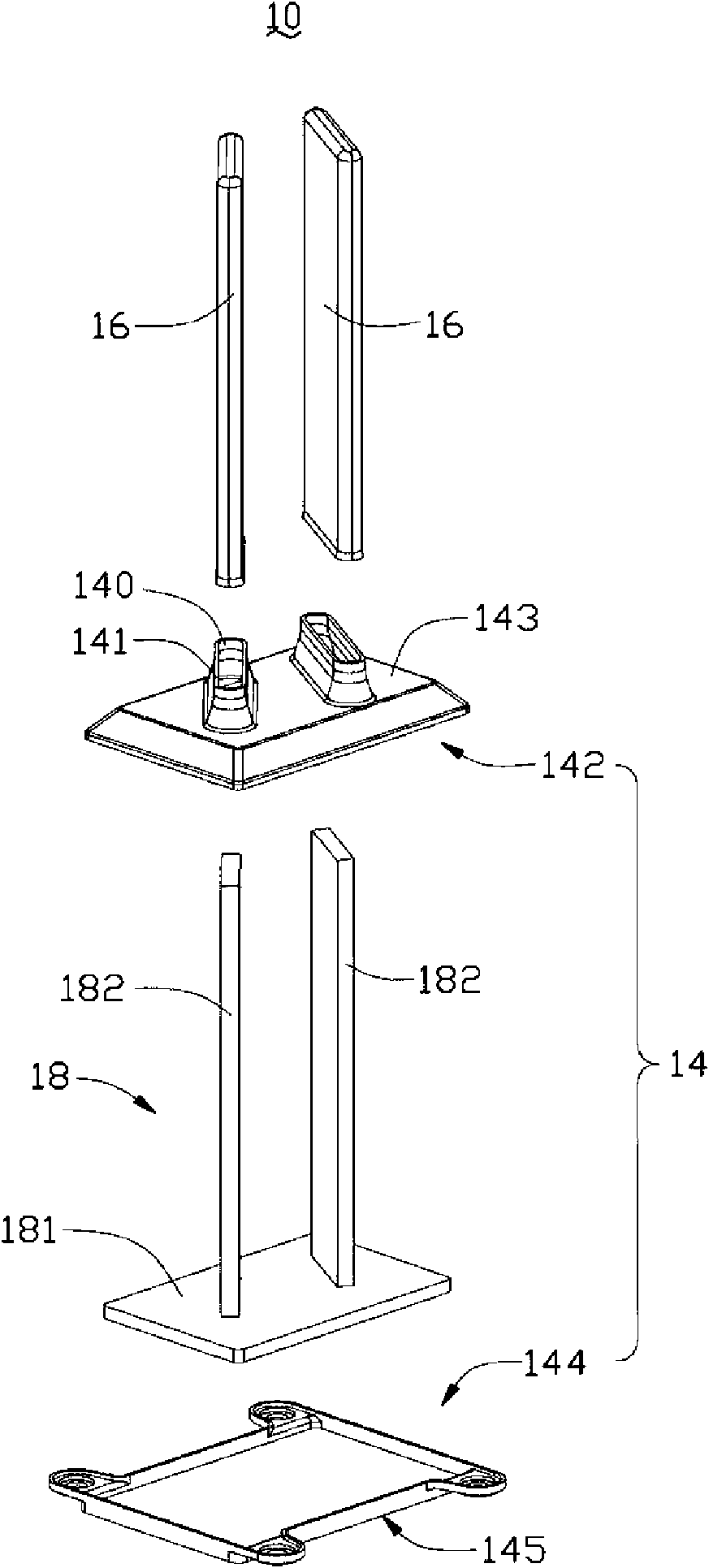
[0013] Please also see image 3 and Figure 4 , the heat transfer body 10 is a hollow structure, and a capillary s...


PUM


Abstract

The invention relates to a heat radiator, which comprises a heat transfer body and a heat radiation body, wherein the heat transfer body is in a hollow structure and is provided with a capillary structure and work liquid, the heat transfer body comprises an evaporation cavity and a condensing cavity, the evaporation cavity and the condensing cavity are hollow and are mutually communicated, the condensing cavity extends upwards from the evaporation cavity, the capillary structure comprises a horizontal part and a vertical part, the horizontal part is pasted on the inner wall of the evaporationcavity, the vertical part upwards extends into the condensing cavity from the horizontal part and is separated from the inner wall of the condensing cavity, a steam passage is formed between the outer periphery of the vertical part and the inner wall of the condensing cavity, and the condensing cavity is penetrated and arranged in the heat radiation body.

Description

technical field [0001] The invention relates to a heat dissipation device, in particular to a heat dissipation device suitable for heat dissipation of electronic components. Background technique [0002] With the rapid development of the computer industry, the CPU pursues high-speed, multi-functional and miniaturized heat dissipation problems are becoming more and more serious. Therefore, the heat must be dissipated in a timely and effective manner, otherwise it will greatly affect the work of electronic components. performance while reducing the life of electronic components. [0003] Most of the current heat dissipation devices use a combination of a solid metal heat-absorbing base plate combined with a circular heat pipe and cooling fins, wherein the evaporation end of the heat pipe is connected to the heat-absorbing base plate, and the condensing end is passed through the heat-dissipating fin. The heat-absorbing bottom plate absorbs the heat generated by the heating ele...

Claims


Application Information

Patent Timeline
Patent Type & Authority Applications(China)
IPC IPC(8): H01L23/427H01L23/367
CPCH01L23/467F28D15/0275H01L2924/0002H01L23/3672H01L23/427F28D15/0266
Inventor 黄清白孟劲功洪锐彣
Owner FURUI PRECISE COMPONENT (KUNSHAN) CO LTD
Why Eureka
Try Eureka