Supercharge Your Innovation With Domain-Expert AI Agents!

Network video releasing method and system thereof

A technology for network video and video capture, applied in the field of network communication, can solve the problems of inability to see the video image of the video capture terminal, difficult to access the video capture terminal, etc.

Inactive Publication Date: 2010-10-20
SHENZHEN WISION TECH HLDG
View PDF2 Cites 12 Cited by
  • Summary
  • Abstract
  • Description
  • Claims
  • Application Information

AI Technical Summary

Problems solved by technology

[0005] In the above two methods, most of the video capture terminals are installed in the local area network, because the external remote client cannot penetrate the local area network or the router used by the client has a firewall, it is difficult to access the video capture terminal, so that the video cannot be seen Collect video images of the area monitored by the terminal

Method used


Image

  • Network video releasing method and system thereof
  • Network video releasing method and system thereof
  • Network video releasing method and system thereof

Examples


Embodiment 1

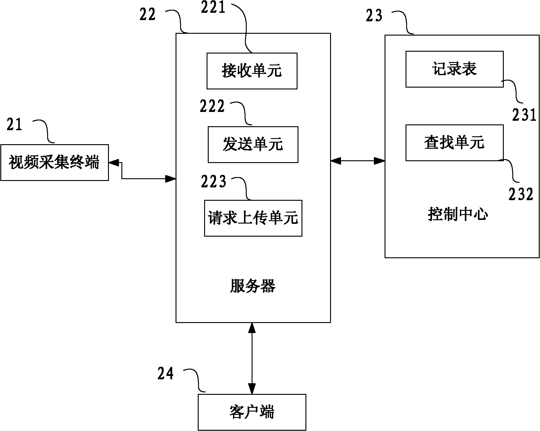
[0035] In this embodiment, as figure 2 As shown, the network video distribution system includes at least one video collection terminal 21 , at least one server 22 and a control center 23 which are connected to each other.

[0036] The video capture terminal 21 is used to capture images of the monitored area, and may be an integrated camera and video server, or a network camera. The server 22 includes a receiving unit 221 , a sending unit 222 and a request uploading unit 223 , and the control center 23 includes a video capture terminal record table 231 and a search unit 232 .

[0037] The video capture terminal 21 has an identification code. When the video capture terminal 21 registers with the server 22, it sends its own identification code, IP address and port number to the server 22, and the server 22 collects the video. The identification code, IP address and port number of the terminal 21 are recorded in the video capture terminal record table 231 of the control center 2...

Embodiment 2

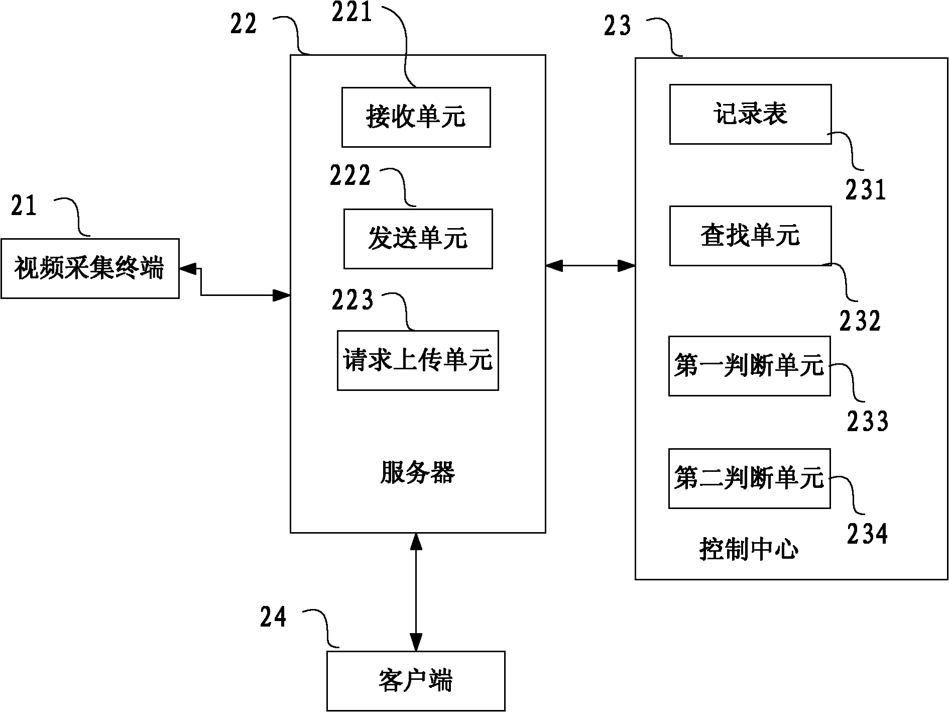
[0043] like image 3 As shown, the difference from the first embodiment is that the control center 23 of the network video distribution system further includes a first judgment unit 233 and a second judgment unit 234, and the first judgment unit 233 judges that the video capture terminal 21 needs to be accessed. Whether the number of clients exceeds the set amount, and if so, the request uploading unit 223 is controlled to send an upload request to the video capture terminal 21 . The video capture terminal cannot withstand simultaneous access by multiple clients. For example, the video capture terminal can accept simultaneous access by up to 10 clients. When the server receives a request from a client to access a video capture terminal, it summarizes the access request into the control system. The center 23, the control center 23 counts the number of clients that require access to the same video capture terminal during this period, and if it exceeds a set amount (for example, ...


PUM


Abstract

The invention discloses a network video releasing method and a system thereof. The network video releasing method comprises the steps that: a server establishes a video acquisition terminal recording table which comprises an identification code of a video acquisition terminal, an IP address and an access mode thereof; the server receives an access request which is sent from a client side and is used for accessing a video acquisition terminal, and the access request comprises the identification code of the video acquisition terminal; the access mode of the video acquisition terminal accessed by the client side is determined, and if the access mode is direct connection, the IP address of the video acquisition terminal is searched according to the identification code, and sent to the client side; and if the access mode of the video acquisition terminal accessed by the client side is backward connection, an upload request is sent to the video acquisition terminal, and the video acquisition terminal is requested to upload a video image and forward the received video image to the client side. The invention leads the client side to be easier to view the video image of the video acquisition terminal.

Description

technical field [0001] The invention relates to the field of network communication, in particular to a method and system for publishing a network video. Background technique [0002] The remote network video surveillance in the prior art usually has the following two methods: [0003] Centralized monitoring. Set up cameras in multiple areas, and use DDN, V.90Modem, ISDN and other access methods based on traditional access methods to conduct remote centralized monitoring in the computer room. This method basically uses a special networking scheme, which requires a large number of streaming media forwarding and other work, and has a designated monitoring terminal, and not any terminal can see the monitoring image. [0004] Point-to-point remote monitoring. Based on ADSL / CableModem point-to-point remote monitoring system, such as home remote monitoring system. Add a video capture card to the PC of the video capture terminal in the monitored area or to the video server, whic...

Claims


Application Information

Patent Timeline
Patent Type & Authority Applications(China)
IPC IPC(8): H04L29/06H04L29/12H04N7/24
Inventor 赵勇
Owner SHENZHEN WISION TECH HLDG
Features
  • R&D
  • Intellectual Property
  • Life Sciences
  • Materials
  • Tech Scout
  • Unparalleled Data Quality
  • Higher Quality Content
  • 60% Fewer Hallucinations
Learn More