Drive unit for a hair cutting machine

A driving device, hair clipper technology, applied in the direction of electromechanical device, magnetic circuit shape/style/structure, metal processing, etc. Optimizing material consumption, saving punching, optimizing the effect of magnetic flux

Active Publication Date: 2010-10-20
WAHL
View PDF3 Cites 0 Cited by
  • Summary
  • Abstract
  • Description
  • Claims
  • Application Information

AI Technical Summary

Problems solved by technology

[0004] The disadvantage of this construction is that the optimum mechanical properties of the drive are not achieved
Furthermore, it is disadvantageous that in such a construction the copper consumption for the field coil and the stamping waste in the silicon steel sheets for the laminated stator and armature are relatively high

Method used


Image

  • Drive unit for a hair cutting machine
  • Drive unit for a hair cutting machine
  • Drive unit for a hair cutting machine

Examples


Embodiment Construction

[0024] Corresponding parts in the following detailed figure description are respectively marked with the same symbols.

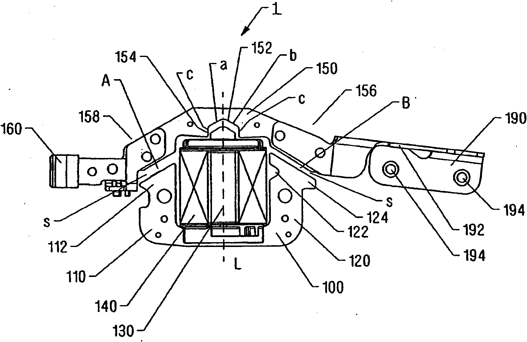
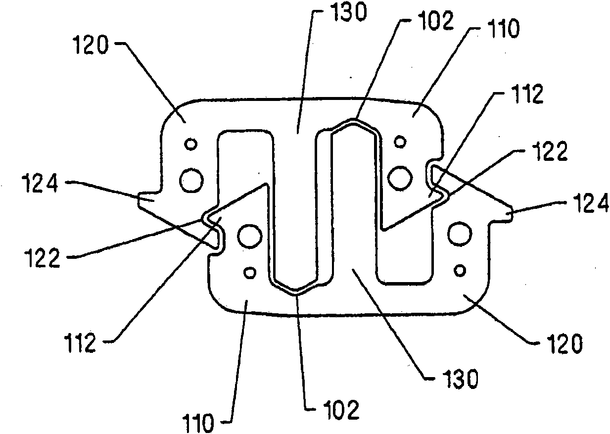
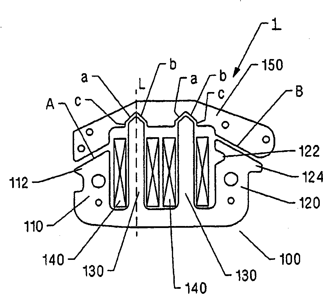
[0025] figure 1 A plan view is shown of a first exemplary embodiment of a drive device according to the invention for a hairdressing machine, which includes a drive motor 1 . The drive motor 1 is composed of a stator 100 having a field coil 140 and an armature 150 arranged corresponding to the stator 100 . The stator 100 is substantially U-shaped with a first leg 110 and a second leg 120 . An additional arm 130 is arranged between the first arm 110 and the second arm 120, on the circumference of which an excitation coil 140 is mounted. The armature 150 is arranged transversely to the ends of the arms 110 , 120 , 130 of the stator 100 , wherein a driver 160 is fixed at a first end 158 and a stand 190 is fixed at a second end 156 . The drive member 160 is configured to vibrate a blade set of the hair clipper and thereby transmit the movement of the armature...


PUM


Abstract

The invention relates to a drive unit for a hair cutting machine, comprising a driving motor (1) that consists of a substantially U-shaped stator (100) which has a first leg (110), a second leg (120), and at least one additional leg (130) located between the first leg (110) and the second leg (120), at least one field coil (140) which can be disposed on the at least one additional leg (130), and an armature (150). Lateral air gap sections (A, B) are formed between the first and second leg (110, 120) and the armature (150) while central air gap sections (a, b) are formed between the additionalleg (130) and the armature (150). The central air gap sections (a, b) and the lateral air gap sections (A, B) extend at an angle from a longitudinal axis (L). A first nose (112), which faces away from the additional leg (130), is arranged at the end of the first leg (110), while a notch (122), which faces the additional leg (130) and corresponds to the first nose (122), is arranged on the second leg (120).

Description

technical field [0001] The invention relates to a drive for a hairdressing machine according to the preamble of claim 1 . Background technique [0002] Such a drive is basically known and comprises a stator, a field coil and an armature. The stator and the armature are here stacked from individual insulating sheet steel layers punched out of silicon steel in order to prevent the generation of eddy currents. The stator is substantially U-shaped and has a first arm and a second arm, while an additional arm is provided, which is arranged between the first arm and the second arm. The field coil is designed as a coil for an electromagnet and can be arranged on the at least one additional arm. Armatures are arranged transversely to the arms of the stator, wherein a lateral air gap portion is formed between the first arm and the armature and between the second arm and the armature, and an intermediate portion is formed between the additional arm and the armature. part of the air...

Claims


Application Information

Patent Timeline
Patent Type & Authority Applications(China)
IPC IPC(8): H02K33/06H02K1/14B26B19/28
CPCB26B19/282H02K33/04
Inventor H·施韦尔S·米勒G·金茨勒
Owner WAHL
Why Eureka
Try Eureka