Flatness error control method for single-point diamond turning method machining large-sized optical elements

A single-point diamond and optical element technology, which is applied in the direction of metal processing machinery parts, metal processing, metal processing equipment, etc., can solve the problems of large flatness error and difficulty in ensuring surface shape accuracy, and achieve reliable and accurate detection and control. , Operational safety effect

Inactive Publication Date: 2011-10-26
HARBIN INST OF TECH
View PDF1 Cites 0 Cited by
  • Summary
  • Abstract
  • Description
  • Claims
  • Application Information

AI Technical Summary

Problems solved by technology

[0003] In order to solve the problems that the existing SPDT method has large flatness errors and difficult to guarantee surface shape accuracy when processing large-size optical elements, the present invention provides a flatness error control method for processing large-size optical elements by single-point diamond milling

Method used


Image

  • Flatness error control method for single-point diamond turning method machining large-sized optical elements
  • Flatness error control method for single-point diamond turning method machining large-sized optical elements
  • Flatness error control method for single-point diamond turning method machining large-sized optical elements

Examples


specific Embodiment approach 1

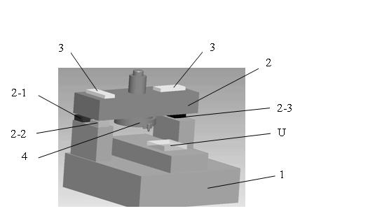
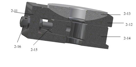
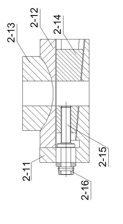
[0014] Specific implementation mode one: according to the instructions attached figure 1 , 2 , 3, 4, 5, 6, 7 and 8 specifically illustrate this embodiment, a method for controlling the flatness error of a single-point diamond milling method for processing large-size optical elements in this embodiment, which is realized based on a processing machine tool , the processing machine tool includes a machine base 1, a flying cutterhead support 2, two digital levels 3 and a flying cutterhead 4, the flying cutterhead 4 is fixed at the center of the flying cutterhead support 2, and the two digital levels 3 is located on the upper surface of the flying cutterhead support 2. The two digital levels 3 are used to calibrate the horizontal position of the flying cutterhead 4, and are also used to measure the deflection angle of the flying cutterhead 4. The bottom of the flying cutterhead support 2 The first wedge-shaped spherical support body 2-1, the second wedge-shaped spherical support b...


PUM


Abstract

The invention relates to a flatness error control method for the single-point diamond turning method machining large-sized optical elements, which relates to the field of the ultraprecision machining of large-sized fragile optical elements. The invention solves the problems that: when the conventional SPDT method machines a large-sized optical element, the flatness error is high, and the surface figure precision can be hardly guaranteed. The flatness error control method first utilizes an interferometer to detect the flatness topography and the flatness error Delta of a large-sized optical element on a bed, the inclination angle of the axis of a fly-cutter head is then calculated according to the flatness error Delta, three wedged spherical supporting bodies are adjusted according to the detected flatness topography, so that the angle of the fly-cutter head can be deflected, the adjusted machine tool is finally utilized to carry out the secondary ultraprecision machining of the optical element, the interferometer is utilized again to redetect the flatness topography and the flatness error Delta, and when the flatness error Delta meets the requirement of a fusion system, flatness error control is fulfilled for the single-point diamond turning method machining the large-sized optical element. The invention is applicable to the machining of the surface figures of large-sized optical elements.

Description

technical field [0001] The invention relates to the field of ultra-precision machining of brittle optical elements, in particular to a flatness error control method for processing large-size optical elements by using a single-point diamond milling (SPDT) method. Background technique [0002] Human beings' heavy dependence on fossil energy is the main cause of environmental degradation, and it is urgent to find new alternative energy sources. Fusion energy is clean, pollution-free and almost inexhaustible. Using laser to control nuclear fusion to obtain energy is an ideal way to solve energy problems in the future. At present, all developed countries attach great importance to it. The laser output by the laser driver requires good beam quality, high enough laser energy and power density. To meet this requirement, a large number of electro-optical and nonlinear optical material components, such as KDP crystal, neodymium glass, K9 glass, Quartz glass etc. The common requireme...

Claims


Application Information

Patent Timeline
Patent Type & Authority Patents(China)
IPC IPC(8): B23C3/00B23Q15/013B23Q15/26
Inventor 梁迎春陈明君李明全张龙江许乔张飞虎王键孙雅洲
Owner HARBIN INST OF TECH
Why Eureka
Try Eureka