Reagent tube cleaning device

A technology for cleaning devices and reagent tubes, applied in the biological field, can solve the problems of insufficient cleaning of reagent tubes, easy slipping, bumping and damage, affecting experimental results, etc., and achieves the effects of stable rotation, tight packaging, and improved cleaning speed.

Inactive Publication Date: 2021-05-28
绍兴市高砚智生物科技有限公司
View PDF7 Cites 0 Cited by
  • Summary
  • Abstract
  • Description
  • Claims
  • Application Information

AI Technical Summary

Problems solved by technology

[0006] Aiming at the deficiencies in the prior art, the present invention provides a reagent tube cleaning device, which solves the problem that in the process of biotechnology operation, the traditional reagent tube cleaning is mostly manual cleaning, the cleaning speed is slow, the outer wall of the reagent tube is smooth, and it is easy to clean. Sliding, bumping and damage, resulting in waste, manual cleaning at the same time, the cleaning is very uneven, there is a problem that some reagent tubes are not cleaned sufficiently, leaving a small amount of residue, which seriously affects the experimental results

Method used


Image

  • Reagent tube cleaning device
  • Reagent tube cleaning device
  • Reagent tube cleaning device

Examples


Embodiment 1

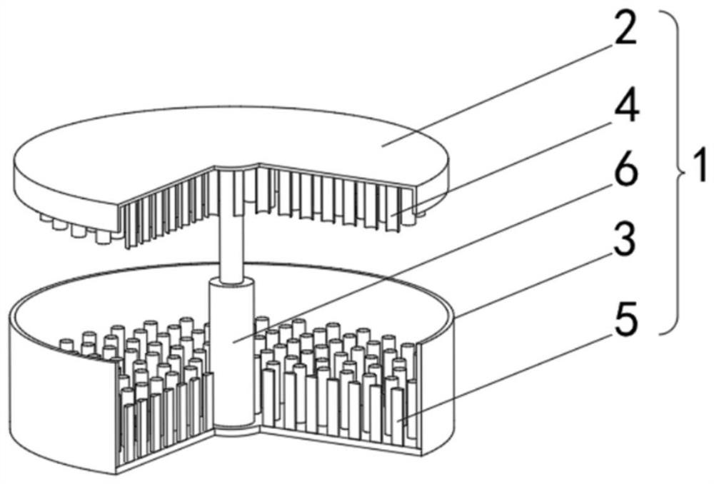
[0042]SeeFigure 1-2 The present invention provides a technical solution: a reagent tube cleaning device including a reagent tube cleaning apparatus body 1 composed of an upper cover 2, a lower tank 3, and a hydraulic telescopic rod 6, and a fixed connection of the inner wall of the upper cover 2 The fixing mechanism 4, the bottom of the lower tank 3 is rotated by the external micro motor, and the top portion of the inner wall of the upper cover 2 is fixed to the top of the hydraulic telescopic rod 4, the bottom portion of the inner wall of the lower tank 3 and the hydraulic telescopic rod 4 The bottom fixed connection.

[0043]The fixing mechanism 4 is located directly above the cleaning mechanism 5, and the fixing mechanism 4 is adapted to the cleaning mechanism 5.

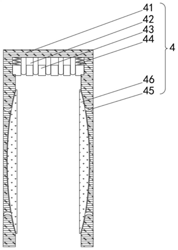
[0044]The fixing mechanism 4 includes a fixing frame 41, and the inner wall top of the fixed frame 41 is fixedly coupled with the inlaid block 42, and the inner sliding connection of the inlay block 42 has the abutment block...

Embodiment 2

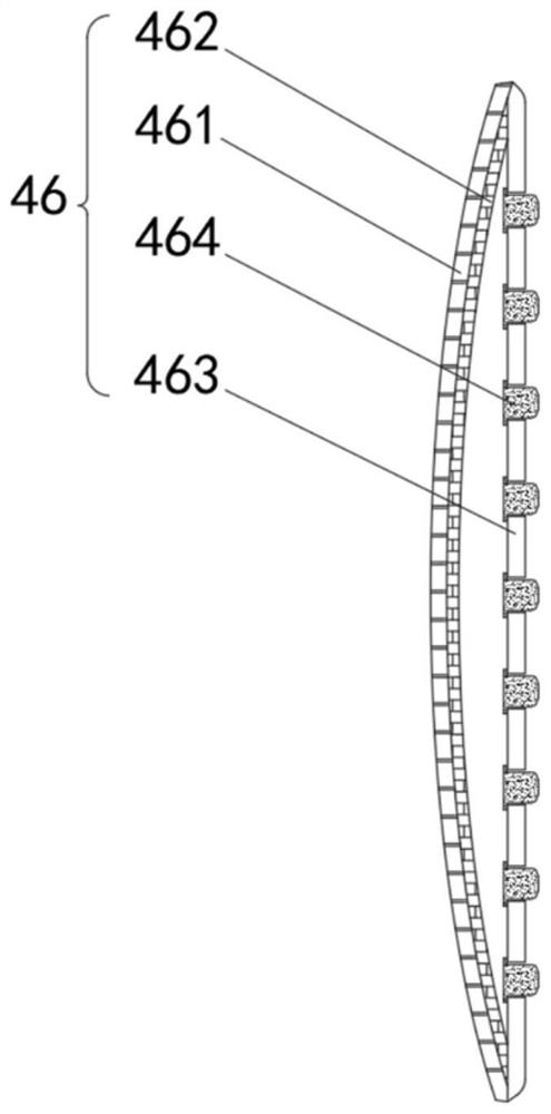
[0047]SeeFigure 1-4 Based on the example one, the present invention provides a technical solution: the anti-slip mechanism 46 includes a receiving strip 461, and the right side of the receiving strip 461 is fixedly connected to the electromagnetic strip 462, the right side of the receiving strip 461 is fixedly connected to the support strip 463. The inside of the support strip 463 is slidably connected to a protective mechanism 464.

[0048]The receiving strip 461 is filled with an inert gas inside the cavity enclosed in the support strip 463, and the electromagnetic strip 462 is in communication with the external power source.

[0049]The protective mechanism 464 includes a magnetic force block 4641, and the right side of the magnetic block 4641 is fixedly connected to the protective frame 4642, and the right side of the protective frame 4642 is fixedly connected to the flexible cotton 4643. The right side of the magnetic block 4641 is fixedly connected to the flexible strip 4644, flexib...

Embodiment 3

[0052]SeeFigure 1-7Based on the first embodiment and the second embodiment, the present invention provides a technical solution: the cleaning mechanism 5 includes a cleaning strip 51, and the bottom of the cleaning strip 51 is rotated by the return sheet 52, and the bottom of the cleaning plate 52 passes The outer micro motor is rotatably connected to the inner portion of the lower tank 3, and the inner side of the cleaning strip 51 is fixed, respectively, respectively, and the top fixed connection of the cleaning strip 51 is fixedly attached, and the outer side fixed connection of the cleaning strip 51 is fixed. There is a cleaning brush 56, and the top of the cleaning plate 52 is fixedly connected to the protective strip 57, and the top of the protective strip 57 extends to the inside of the cleaning strip 51 and is fixed to the cleaning strip 51.

[0053]The cleaning brush 56 includes a fluid plate 561, and the inside of the flow guide plate 561 is opened, and the right side of the ...


PUM


Abstract

The invention discloses a reagent tube cleaning device, which comprises a reagent tube cleaning device body composed of an upper closing cover, a lower closing groove and a hydraulic telescopic rod; the top of the inner wall of the upper closing cover is fixedly connected with a fixing mechanism; the bottom of the lower closing groove is rotatably connected with a cleaning mechanism through an external micro motor; the top of the inner wall of the upper closing cover is fixedly connected with the top of the hydraulic telescopic rod; the bottom of the inner wall of the lower closing groove is fixedly connected with the bottom of the hydraulic telescopic rod; and the fixing mechanism is located directly above the cleaning mechanism. The invention relates to the technical field of biotechnology. The reagent tube cleaning device provided by the invention solves the problems that in the biotechnology operation process, traditional reagent tube cleaning is mostly conducted manually, the cleaning speed is low, the outer walls of reagent tubes are smooth, the reagent tubes are prone to slipping, bumping and damage during cleaning, waste is caused, meanwhile, manual cleaning is carried out and cleaning is not uniform, individual reagent tubes are not cleaned sufficiently, a small amount of residues are left, and an experiment result is seriously influenced.

Description

Technical field[0001]The present invention relates to the field of biotechnology, and is specifically a reagent tube cleaning device.Background technique[0002]Biotechnology is also known as biological engineering, based on life science, using the characteristics and functions of organisms, and construct new species, new varieties (lines), and combined with the principle of engineering, processing production purposes, In recent years, in recent years, in recent years, with the development of modern biotechnology, including genetic engineering, cell engineering, protein engineering, enzyme engineering, and biochemical engineering, producing chemical industry Products, especially new products that are difficult to obtain in general chemical methods, change existing processes, solve two difficult problems with long-term troubled energy crisis and environmental pollution, and become more concerned about people, and some have been put into reality.[0003]According to Chinese Patent CN11056...

Claims


Application Information

Patent Timeline
Patent Type & Authority Applications(China)
IPC IPC(8): B08B9/36B08B13/00
CPCB08B9/0808B08B9/36B08B13/00
Inventor 费小涛
Owner 绍兴市高砚智生物科技有限公司
Why Eureka
Try Eureka