Time sharing multiplex measurement system and method based on vector network analyzer

A technology of vector network analysis and time-division multiplexing, applied in the field of radio frequency microwave industry, can solve the problems of wasting time and users occupying the vector network analyzer for a long time, and achieve the effect of reducing cost, shortening time consumption and improving efficiency

Inactive Publication Date: 2010-10-27
XIDIAN UNIV
View PDF0 Cites 25 Cited by
  • Summary
  • Abstract
  • Description
  • Claims
  • Application Information

AI Technical Summary

Problems solved by technology

If it is used by multiple users, the second user will not be able to use it until the first user finishes measuring, and the subsequent users will continue to wait, which is a great waste of time
For example, when measuring the antenna, first connect the antenna to a port of the vector network analyzer. After calibration, the standing wave of the antenna can be directly measured. However, in the production line, due to the large number of products to be measured, it is impossible to configure data A vector network analyzer is used to test a device. It needs to be installed, calibrated, measured and disassembled before testing the second device. This method is a waste of time.
If the RF device to be tested needs to be continuously debugged and modified to obtain satisfactory results, for example, for the measurement of rectangular waveguide filters, after the user connects and calibrates, the S parameter must be measured every time the depth of the reactive pin is changed. There will be a situation where a user occupies the vector network analyzer for a long time, which limits the improvement of efficiency in the production line

Method used


Image

  • Time sharing multiplex measurement system and method based on vector network analyzer
  • Time sharing multiplex measurement system and method based on vector network analyzer
  • Time sharing multiplex measurement system and method based on vector network analyzer

Examples


Embodiment Construction

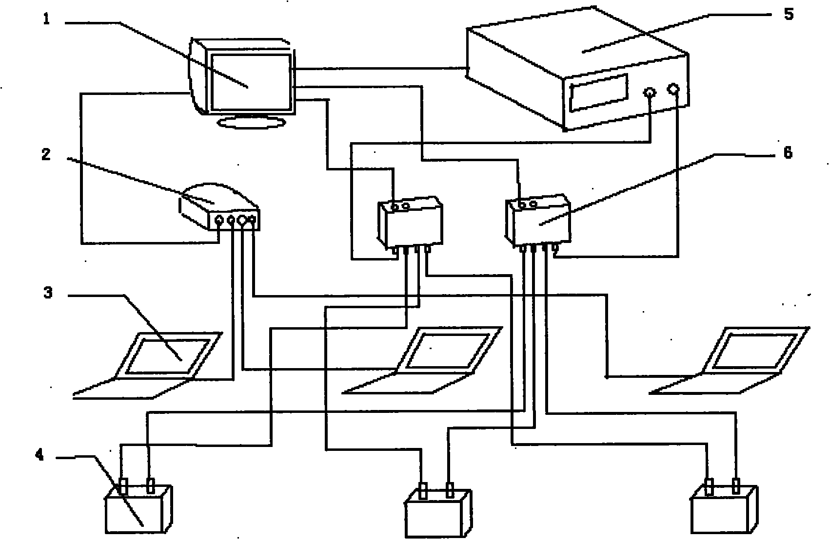
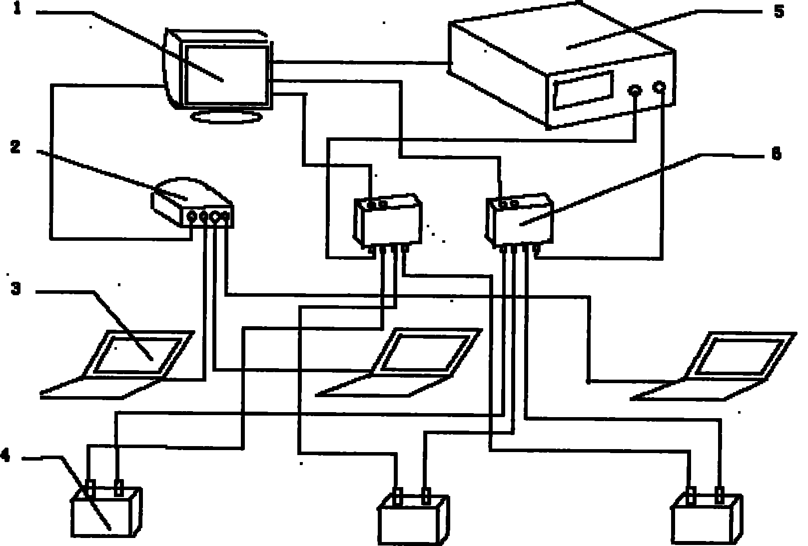
[0027] combine figure 1 , The time-division multiplexing measurement system of the present invention includes a main control computer 1, a router 2, a vector network analyzer 5, two radio frequency multiplex switches 6 and multiple user PCs 3. The main control computer 1 is connected with the control ends of two radio frequency multi-way switches 6, and is used to switch between different users to select the corresponding device under test; the main control computer 1 is connected with the vector network analyzer 5, and is used to control the vector The network analyzer 5 performs measurement; the main control computer 1 is connected with the router 2, and is connected with the user PC 3 through the local area network, and is used to control the main control computer 1 by the user; the input terminals of the two radio frequency multiplex switches 6 are respectively connected The two measurement ports of the vector network analyzer 5 and its multiple output terminals are distri...


PUM


Abstract

The invention discloses time sharing multiplex measurement system and method based on a vector network analyzer, mainly solving the problems of high configuration cost and low efficiency of the prior art. The measurement system realizes multi-user sharing of one vector network analyzer through a vector network analyzer, a main control computer, a router, two radio-frequency multi-way switches and a plurality of user PCs. The measurement method comprises the steps of: firstly, grouping output ends of the radio-frequency multi-way switches; secondly, establishing a connection between the main control computer and the user PCs; thirdly, realizing the control on the main control computer by operating the PCs to ensures that the main control computer firstly controls the radio-frequency multi-way switches to be switched into a radio-frequency element of the user; fourthly, controlling the vector network analyzer to feed measurement data for the user; and fifthly, after the measurement is finished, carrying out corresponding processing on the data on the PCs by the user. Compared with the prior art, the invention reduces the cost of configuring production line apparatus, reasonably utilizes traditional resources, shortens the time, and improves the efficiency.

Description

technical field [0001] The invention belongs to the field of test and measurement, relates to the use of a vector network analyzer, and is mainly used in the measurement and automatic control of the radio frequency microwave industry and other industries. Background technique [0002] The vector network analyzer is an indispensable instrument for the RF microwave industry, but its cost is expensive. The vector network analyzer used in R&D and production generally has a frequency range of several hundred kHz to tens of GHz, and the price of the simplest configuration Also in the tens of thousands of dollars or more. For microwave radio frequency production enterprises, each production line is equipped with several such devices, and the corresponding cost is huge. [0003] Currently, the use of vector network analyzers is single-user operation, that is, one-to-one. When measuring a radio frequency device, it is necessary to calibrate the vector network analyzer first, then c...

Claims


Application Information

Patent Timeline
Patent Type & Authority Applications(China)
IPC IPC(8): G01R27/06G01R27/26
Inventor 侯建强牛中奇凌强
Owner XIDIAN UNIV
Why Eureka
Try Eureka