Unit programmable logic controller

A programming controller and basic unit technology, applied in the direction of program control, electrical program control, general control system, etc., can solve the problems of waste, expensive idle parts of the basic unit, poor operability, etc.

Active Publication Date: 2010-10-27
MITSUBISHI ELECTRIC CORP
View PDF1 Cites 9 Cited by
  • Summary
  • Abstract
  • Description
  • Claims
  • Application Information

AI Technical Summary

Problems solved by technology

However, in general applications that do not require special functional units, the connection board connected to the CPU board, the flat cable, the intermediary board connected to the connection board, and the connector are unnecessary devices, and the existing basic unit will become a surplus. Disadvantages of large, expensive installations of components
In addition, even if the short-distance serial communication in the control device is not used by the special function unit, it is necessary to replace the relay board with a relay communication board, which has the problems of poor operability and waste due to discarding the relay board

Method used


Image

  • Unit programmable logic controller
  • Unit programmable logic controller
  • Unit programmable logic controller

Examples


Embodiment approach 1

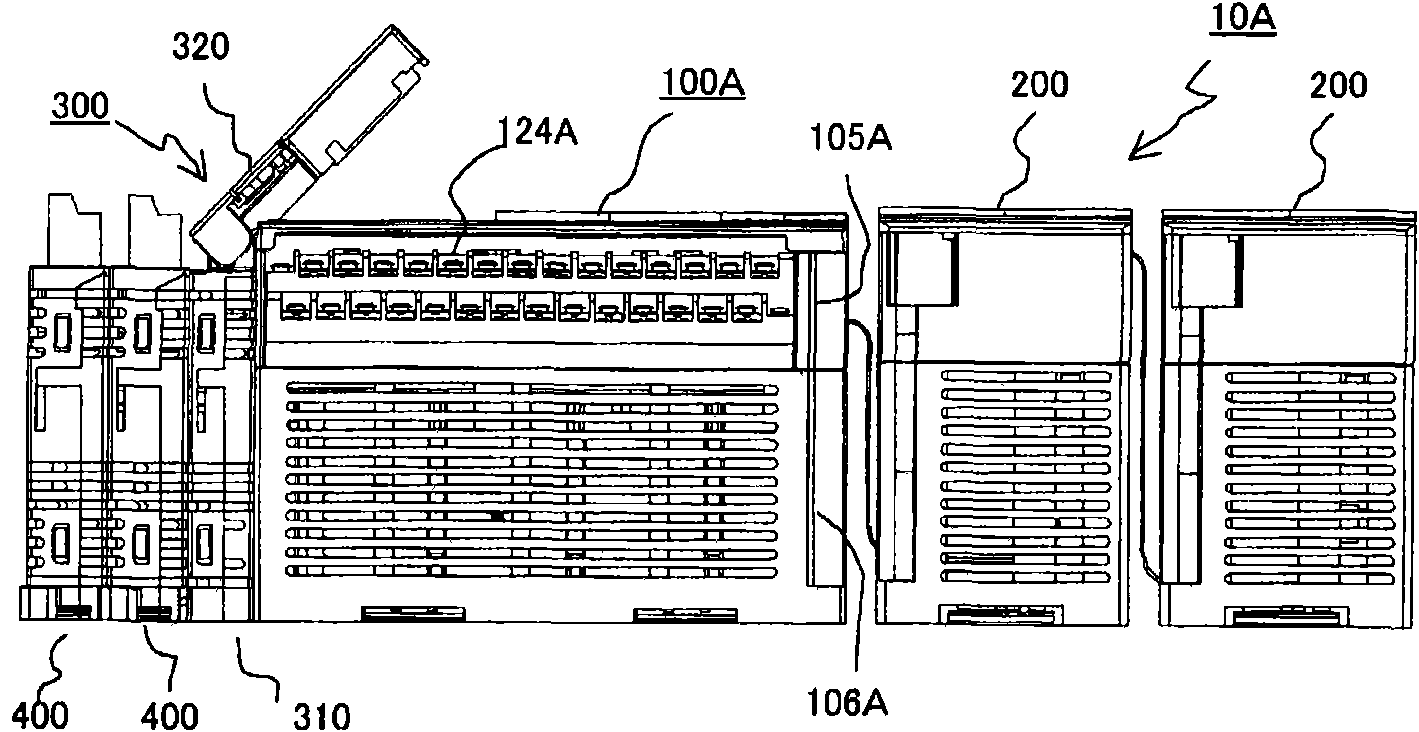
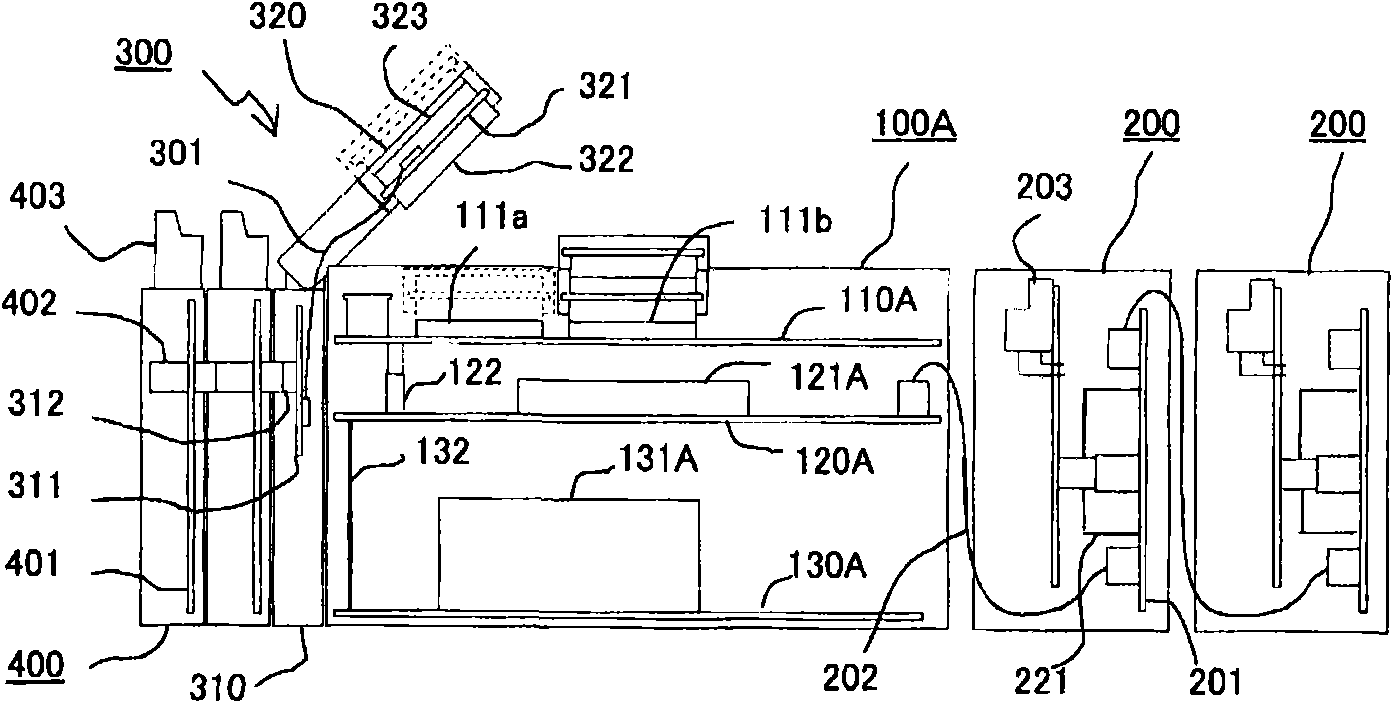
[0036] figure 1 is an external view showing the configuration of the programmable controller in Embodiment 1 of the present invention, figure 2 It is a diagram showing the connection structure of printed circuit boards.

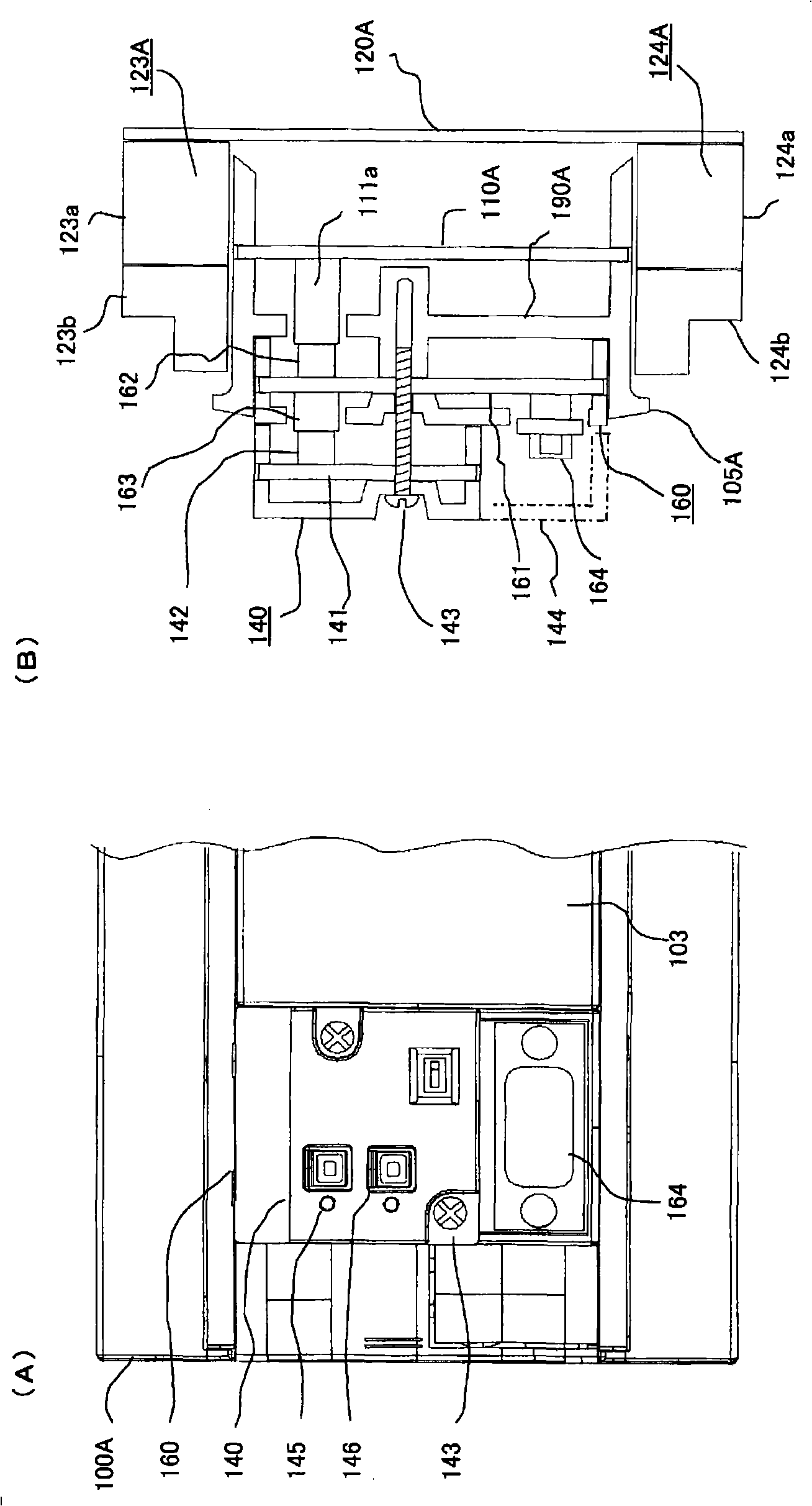
[0037] figure 1 , figure 2 Among them, the basic unit 100A includes: a basic case member 106A whose bottom surface is fixed to a wall surface; and a basic cover member 105A which is fixed to an opening of the basic case member. The internal assembly of the basic casing member 106A is fixed with: a power supply substrate 130A on which a constant voltage power supply circuit component 131A is mounted, and an input / output interface circuit component 121A and input / output terminal boards 123A and 124A (refer to image 3 , Figure 4 ) of the input and output substrate 120A. The CPU board 110A is assembled and fixed inside the basic cover member 105A, and the CPU board 110A, the input / output board 120A, and the power board 130A are connected to each other th...

Embodiment approach 2

[0132] with figure 1 , figure 2 Focusing on the differences, to an external view of the structure of the unit type programmable controller 10B according to Embodiment 2 of the present invention Figure 10 and as a sectional view of Figure 11 Be explained. In addition, the same code|symbol in each figure shows the same or a corresponding part.

[0133] Figure 10 , Figure 11 Among them, the basic unit 100B includes: a basic casing member 106B whose bottom surface is fixed to a wall surface, and a basic cover member 105B that is fixed to an opening of the basic casing member.

[0134] Inside the basic housing member 106B, there are assembled and fixed: a power supply board 130B on which a constant voltage power supply circuit part 131B is mounted, and an input / output interface circuit part 121B for on / off control and input and output terminal boards 123B and 124B. output substrate 120B.

[0135] A CPU substrate 110B is assembled and fixed inside the basic cover member ...


PUM


Abstract

The invention relates to a unit programmable logic controller which relieves the load of a basic unit and is connected to a multifunctional expanding unit. A plurality of expanding units (400) are orderly connected backwards in a medium unit (300) having a frame part (310) and a bridge part (320) and are arranged on left end of a basic unit (100A) having a CPU substrate (110A) inside, wherein an adapter connector (111a) arranged on the CPU substrate (110A) is connected to a second adapter as a limited specification of the expanding units (400) or a first preceding connector and a second preceding connector arranged at the bridge part (320); the first preceding connector (322) is connected to the expanding units (400) through a backwards connector (312) hidden in the frame part (310); and the first adaptor is superposed on the second preceding connector (323).

Description

technical field [0001] The present invention relates to a unit-shaped programmable controller without a motherboard. In addition to connecting a basic unit with a built-in microprocessor and an input-output extension unit connected to the basic unit, the unit-shaped programmable controller also has a mixed Connect expansion units with various functions. Background technique [0002] Built-in microprocessor, corresponding to the operating state of the input signal of the operation switch and various sensors, and the sequence program stored in the program memory, it is a unit-shaped programmable unit that performs drive control of various actuators and electrical loads such as display devices. In the controller, in addition to corresponding to the normal on / off input and output control, in order to correspond to various applications that require special functions such as input and output of analog signals, input and output of serial signals for communication, or input and outp...

Claims


Application Information

Patent Timeline
Patent Type & Authority Applications(China)
IPC IPC(8): G05B19/05
CPCG05B19/0423G05B2219/25314G06F13/409G05B19/054
Inventor 细川文哉
Owner MITSUBISHI ELECTRIC CORP
Why Eureka
Try Eureka