Road measuring method, device and non-stop charging system

A drive test device and drive test technology, applied in the direction of measurement devices, radio wave measurement systems, and the use of re-radiation, can solve problems such as signal interference and loss, and achieve the effect of ensuring the success rate

Active Publication Date: 2010-10-27
BEIJING WANJI TECH
View PDF4 Cites 51 Cited by
  • Summary
  • Abstract
  • Description
  • Claims
  • Application Information

AI Technical Summary

Problems solved by technology

[0006] The embodiment of the present invention provides a road test method, device and non-stop toll collection system to solve the problem

Method used


Image

  • Road measuring method, device and non-stop charging system
  • Road measuring method, device and non-stop charging system
  • Road measuring method, device and non-stop charging system

Examples


Embodiment 1

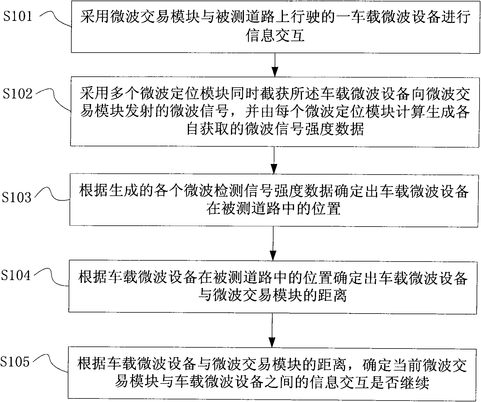
[0030] Such as image 3 As shown, a drive test method of this embodiment includes: using a microwave transaction module to interact with a vehicle-mounted microwave device running on the tested road (step S101); using multiple microwave positioning modules to simultaneously intercept the vehicle The microwave equipment transmits the microwave signal to the microwave transaction module, and each microwave positioning module calculates and generates the microwave signal intensity data (step S102); according to the generated intensity data of each microwave detection signal, it is determined that the vehicle-mounted microwave equipment is being Measure the position on the road (step S103); determine the distance between the on-board microwave device and the microwave transaction module according to the position of the on-board microwave device on the measured road (step S104); determine the current position according to the distance between the on-board microwave device and the micr...

Embodiment 2

[0033] Such as Figure 5 As shown, this is a drive test method of this embodiment. The method includes: adopting multiple microwave transaction modules arranged at intervals along the cross section of the tested road to simultaneously perform information interaction with a vehicle-mounted microwave device running on the tested road (step S201); Multiple microwave positioning modules arranged at intervals along the measured road cross section are used to simultaneously intercept microwave signals transmitted by the vehicle-mounted microwave equipment to multiple microwave trading modules, and each microwave positioning module calculates and generates the microwave signal strength data obtained separately (Step S202); Determine the position of the vehicle-mounted microwave equipment on the measured road according to the generated data of the intensity of each microwave detection signal (Step S203); Determine the vehicle-mounted microwave equipment and each vehicle based on the loca...

Embodiment 3

[0042] Such as Figure 7 with Figure 8 As shown, the drive test device of this embodiment includes: a microwave transaction module 100 and a plurality of microwave positioning modules 200; wherein, the microwave transaction module 100 includes: an information interaction unit 101 for communicating with a vehicle-mounted microwave device running on the tested road Information exchange; the position information generating unit 102 is used to determine the position of the vehicle-mounted microwave equipment on the measured road according to the acquired strength data of each microwave detection signal; the distance information generating unit 103 is used to determine the position of the vehicle-mounted microwave equipment on the measured road according to the The position in determines the distance between the vehicle-mounted microwave device and the microwave transaction module; the information interaction selection unit 104 is configured to determine whether the information inter...


PUM


Abstract

The invention relates to a road measuring method, a device and a non-stop charging system. The method comprises the following steps: adopting a microwave transaction module for carrying out information interaction with on-vehicle microwave equipment running on a road to be measured; adopting a plurality of microwave positioning modules for simultaneously intercepting and capturing the microwave signals sent by the on-vehicle microwave equipment to the microwave transaction module; using each microwave positioning module for calculation to generate the respectively obtained microwave signal intensity data; determining the position of the on-vehicle microwave equipment in the road to be measured according to each generated microwave detection signal intensity datum; determining the distancefrom the on-vehicle microwave equipment to the microwave transaction module according to the position of the on-vehicle microwave equipment in the road to be measured; and determining whether the information interaction between the current microwave transaction module and the on-vehicle microwave equipment can be continued or not according to the distance from the on-vehicle microwave equipment to the microwave transaction module. The invention aims at solving the problems of signal interference and lack when the on-vehicle microwave equipment in an electronic charging system is positioned inthe edge of a communication region, and solving the problem of low accuracy of the pike charging caused by signal interference and lack.

Description

Technical field [0001] The present invention relates to the technical field of electronic toll collection on expressways, particularly to the road test technology in the electronic toll collection system, and specifically to a road test method, device and e-toll collection system. Background technique [0002] Electronic Toll Collection (ETC: Electronic Toll Collection) system is also called e-toll collection system. The ETC system uses dedicated Short-Range Communication (DSRC: Dedicated Short-Range Communication) technology to complete the entire charging process, so that the vehicle remains in a driving state during the entire charging process without parking. [0003] The ETC system in the prior art includes: equipment racks, roadside equipment (RSU) and on-board equipment (OBU). Such as figure 1 As shown, a plurality of roadside devices (20a, 20b, 20c) can be installed on the device rack 10, and the in-vehicle device 30 is installed on a moving vehicle. The roadside devices ...

Claims


Application Information

Patent Timeline
IPC IPC(8): G07B15/00G01S11/06
Inventor 田林岩王春生邓永强武宏伟
Owner BEIJING WANJI TECH
Why Eureka
Try Eureka