Flow divider for nose

A shunt and machine head technology, which is applied in the direction of insulating conductors/cables, can solve the problems of inconvenient and stable production, difficulty in ensuring product quality, and damage to the equilibrium state, and achieve thickness and uniformity guarantee, function improvement, and stable production. Effect

Inactive Publication Date: 2010-10-27
上海旭东电工机械厂
View PDF0 Cites 15 Cited by
  • Summary
  • Abstract
  • Description
  • Claims
  • Application Information

AI Technical Summary

Problems solved by technology

However, when the flow speed is accelerated, the original equilibrium state will be destroyed and additiona...

Method used


Image

  • Flow divider for nose
  • Flow divider for nose
  • Flow divider for nose

Examples


Embodiment Construction

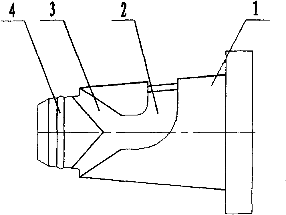
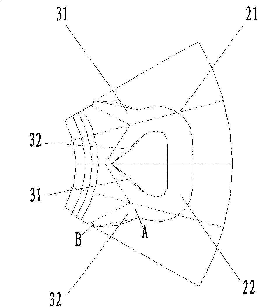
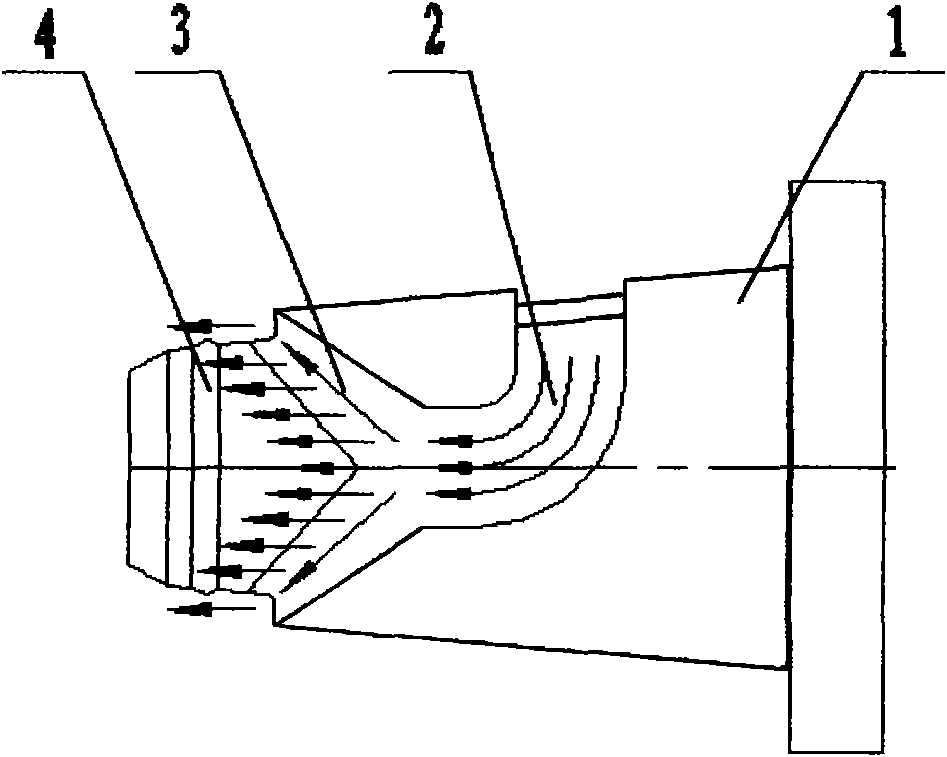
[0019] Such as Figure 1 to Figure 4 As shown, the head splitter of the present invention includes a splitter body 1, and a flow channel group is provided on the surface of the splitter body 1, and the flow channel group includes a first flow channel composed of two flow channels 21 and 22 in a bifurcated shape. In group 2, a second flow channel group 3 formed of two flow channels 31 and 32 in a bifurcated shape is respectively opened at the end of each flow channel 21, 22 of the first flow channel group 2.

[0020] Wherein, the diverter body 1 is cylindrical or conical, and the taper of the conical diverter body is 1°˜10°. The two runners 21 and 22 of the first runner group form an included angle of a certain degree; the two runners of the second runner group 3 also form an included angle of a certain degree. The groove is arc-shaped, and the outflow is evenly balanced. The connecting line between the end of the first group of flow channels and the end of the second group o...


PUM

PropertyMeasurementUnit
Taperaaaaaaaaaa

Abstract

The invention discloses a flow divider for a nose, comprising a conical or cylindrical flow divider body, wherein a flow way set is arranged on the surface of the flow divider body and comprises a first flow way set formed by two flow ways in a bifurcation way, and the tail end of each flow way in the first flow way set is provided with a second flow way set formed by two flow ways in a bifurcation way. The depth of the flow ways are from deep to shallow so that the pressure can be fully released when a molten body is extruded. The two sets of flow ways have smooth transition, and the bottom sides of grooves are in a circular-arc shape. A circular arc-shaped grading ring is arranged between the second flow way set and an outlet of the flow divider body. The invention can reduce the material flowing resistance of a molten plastic polymer in the process of passing through the flow divider to a nose mouth mould so that the pressure is fully released, and therefore, the invention has the advantages of balanced flow, stable volume, uniform flowing speed and constant temperature, thereby ensuring the stability of product quality.

Description

technical field [0001] The invention relates to a shunt, in particular to a shunt at the head of a wire and cable extruder. Background technique [0002] At present, the design method adopted for the flow channel of the head shunt of the known wire and cable extruder is: the surface of the shunt is designed to be divided into two forms, and the flow is not easy to control. When the melted plastic polymer flows slowly in the flow channel, it is necessary to manually adjust the gap between the shunt and the shell to ensure the stability of the product. However, when the flow speed is accelerated, the original equilibrium state will be destroyed and additional adjustments are required, which is not convenient for stable production and difficult to guarantee product quality. Contents of the invention [0003] In order to solve the above technical problems, the present invention provides a die splitter capable of maintaining a balanced flow of melt and improving product qualit...

Claims


Application Information

Patent Timeline
IPC IPC(8): H01B13/14B29C47/70
Inventor 董建平
Owner 上海旭东电工机械厂
Why Eureka
Try Eureka