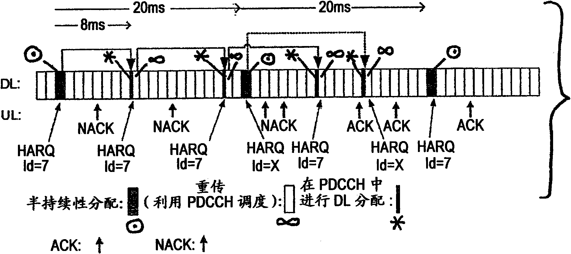
Improved re-transmission capability in semi-persistent transmission
A semi-persistent scheduling, hybrid automatic retransmission technology, applied in transmission systems, digital transmission systems, error prevention/detection using return channels, etc., can solve problems such as increasing UE complexity and storage requirements
- Summary
- Abstract
- Description
- Claims
- Application Information
AI Technical Summary
Problems solved by technology
Method used
Image
Examples
Embodiment approach 1
[0089] Embodiment 1A: PDCCH signaling can signal X number of HARQ processes (for example, X=8 using 3 bits). One of the values of X indicates semi-persistent HARQ scheduling. The number of HARQ processes for the semi-persistent case is given by N and this number is signaled via RRC signaling with one HARQ process ID indicating semi-persistent. A HARQ buffer indicating semi-persistent (eg, buffer 7 when X=8) is divided into N sub-buffers (eg, 7, 8, . . . , 7+N-1). Since semi-persistent allocation is more suitable for traffic with small packets, such as VoIP, it is assumed that the size of these sub-buffers is sufficient for semi-persistent traffic. Then for each semi-persistent allocation (for new packets), the subbuffer identification can be implicitly derived from the periodic pattern, the number of TTIs and the number of HARQ buffers reserved for semi-persistent use. One such equation is as follows:
[0090] sub-buffer=[trunc(current_TTI / SP_period)]modNumber_of_semi-per...
Embodiment approach 2
[0095] Embodiment 2A: In the PDCCH, one of X HARQ processes may be signaled (for example, X=8 using 3 bits). One of these X values indicates that the parameters in the PDCCH are used for semi-persistent allocation. The number of HARQ processes used for semi-persistent is N and this value is signaled via RRC signaling with one HARQ process ID indicating semi-persistent eg last HARQ buffer X-1. The HARQ buffer is divided into X+N-1 buffers, which do not need to be of equal size, eg smaller sized buffers may be sufficient for semi-persistent allocation. Then if the PDCCH indicates semi-persistent via the HARQ process ID, or if semi-persistent allocation is in use, the correct HARQ buffer for semi-persistent transmission of new packets can be derived from the following equation:
[0096] HARQ buffer=X-1+[trunc(current_TTI / SP_period)]modNumber_of_semi-persistent_HARQ
[0097] For the retransmission of semi-persistent allocation, several possible signaling schemes are given in t...
Embodiment approach 3
[0098] Embodiment 3A: PDCCH signaling can transmit X HARQ processes. Multiple HARQ processes and HARQ IDs are reserved for semi-persistent. One of them indicates the semi-persistence in the initial allocation to identify that the semi-persistence is in use. All these HARQ IDs form a HARQ process vector Y. The HARQ process used in the case of semi-persistent allocation can be derived, for example, from the following equation:
[0099] vector_index=[trunc(current_TTI / SP_period)]modNumber_of_semi-persistent_HARQ
[0100] HARQ buffer=Y(vector_index)
[0101] For retransmissions of semi-persistent allocations, possible signaling schemes are described with reference to embodiments 1B, 2B, 3B and 4B.
PUM
 Abstract
Description
Claims
Application Information
 - R&D
- Intellectual Property
- Life Sciences
- Materials
- Tech Scout
- Unparalleled Data Quality
- Higher Quality Content
- 60% Fewer Hallucinations
Browse by: Latest US Patents, China's latest patents, Technical Efficacy Thesaurus, Application Domain, Technology Topic, Popular Technical Reports.
© 2025 PatSnap. All rights reserved.Legal|Privacy policy|Modern Slavery Act Transparency Statement|Sitemap|About US| Contact US: help@patsnap.com


