Brake device for an elevator and elevator device

A braking device and elevator technology, applied in transportation, packaging, elevators, etc., can solve the problems of increasing device capacity, braking force influence, lifting body skew, etc., to achieve miniaturization, high reliability, and low cost Effect

Active Publication Date: 2010-11-03
HITACHI LTD
View PDF4 Cites 5 Cited by
  • Summary
  • Abstract
  • Description
  • Claims
  • Application Information

AI Technical Summary

Problems solved by technology

[0006] However, in the above-mentioned prior art, since the actuator is installed at one end of the connecting rod and the structure of the brake is installed at the other end of the connecting rod, when the braking device brakes, both sides of the lifting body The reaction force generated when the brake part is clamped between the guide rail and the armature acts on the lifting body in the direction away from the guide rail, and acts on the guide rail in the direction away from the lifting body, which causes the lifting body to skew, or makes the guide rail The mounting position is shifted, so it is not preferred
[0007] In addition, since the movable brake member is provided only on one side, there is a problem that the capacity of the device for securing the flexibility of the brake elastic body has to be increased in order to exert the required braking force.
Although it is conceivable to reduce the amount of deflection by using a braking elastic body with a high spring constant to ensure the required braking force, even a small change in the amount of deflection will affect the braking force when this method is adopted. Power has a large impact, so the size of each part needs to be strictly managed

Method used


Image

  • Brake device for an elevator and elevator device
  • Brake device for an elevator and elevator device
  • Brake device for an elevator and elevator device

Examples


Embodiment 1

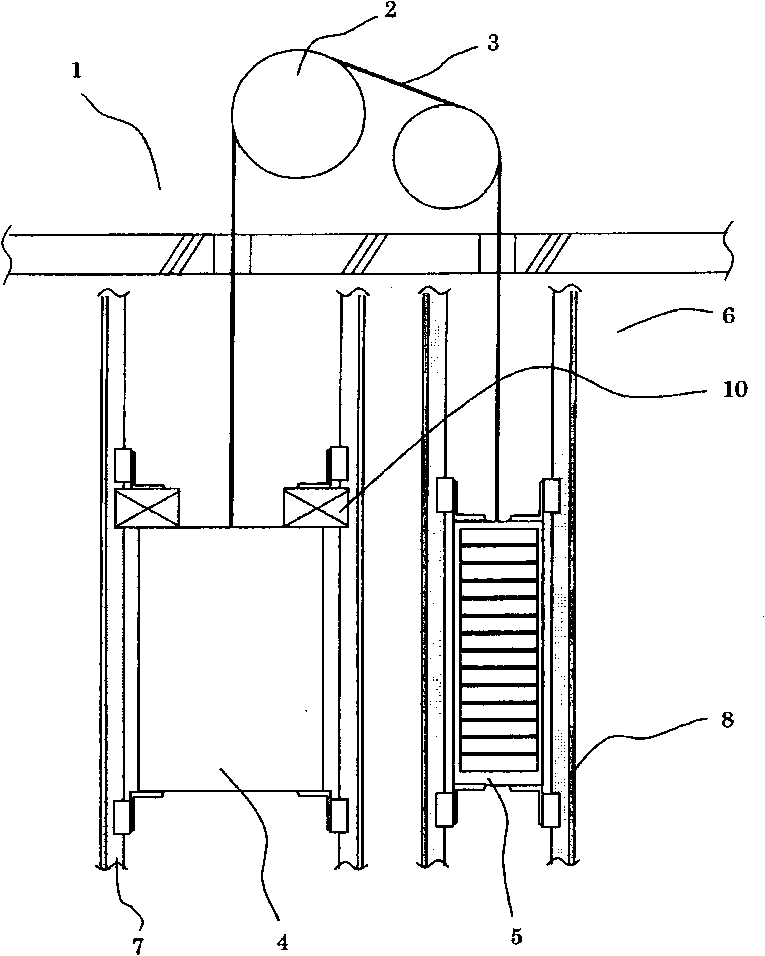
[0051] Such as figure 1As shown, in the elevator, the hoist is arranged in the machine room 1, the sling 3 is wound on the sheave 2 of the hoist, and the elevator car 4 and the counterweight 5 are connected to the two ends of the sling 3 respectively. In the lifting passage 6, the elevator car 4 is guided by the elevator car side guide rail 7, and the counterweight 5 is guided by the counterweight side guide rail 8. By rotating the sheave 2 of the hoist, the elevator car 4 and the counterweight 5 are raised and lowered. Go up and down in channel 6. The braking device 10 of the present embodiment is fixed to the upper portion of the elevator car 4 with unillustrated bolts.

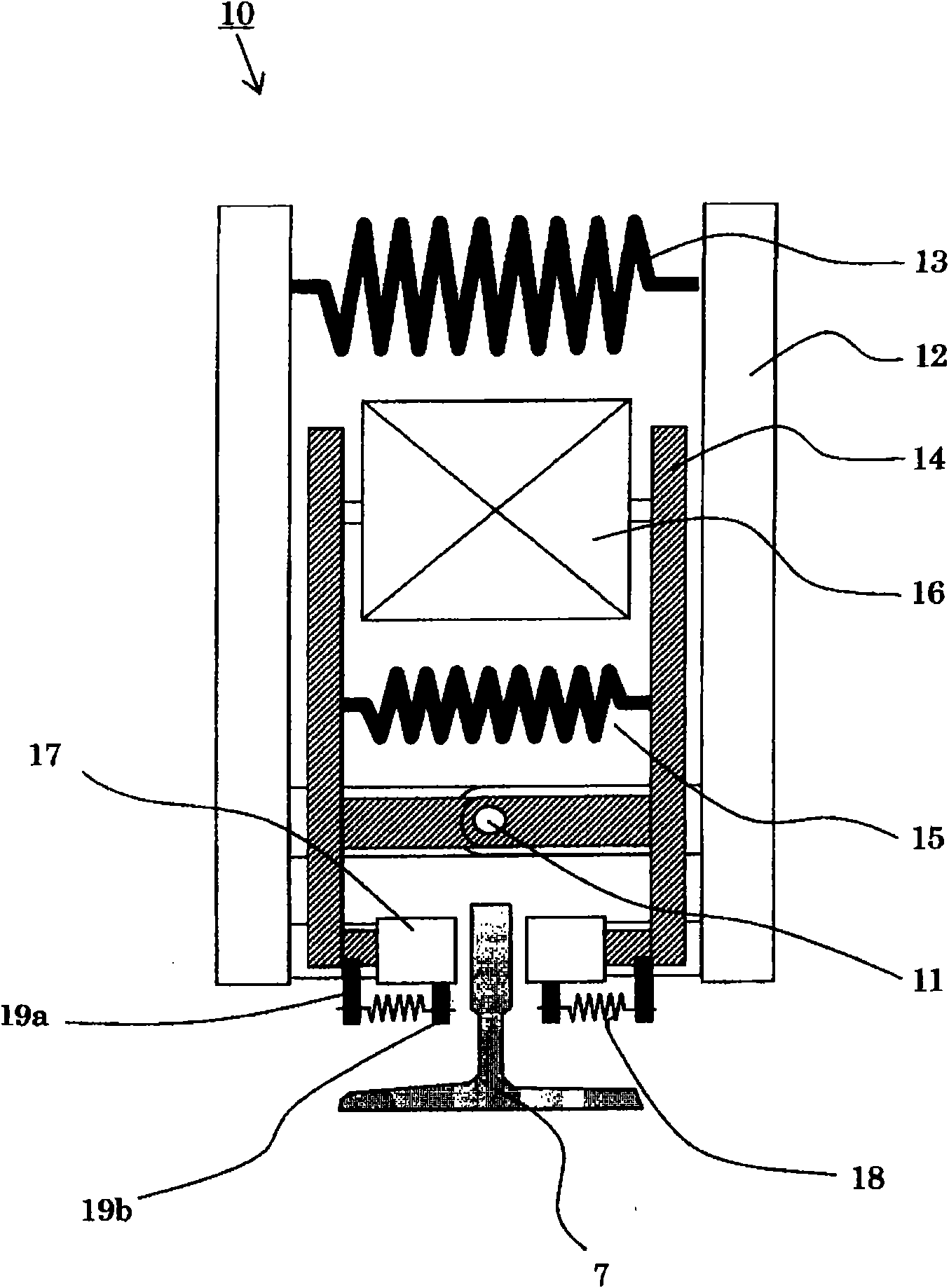
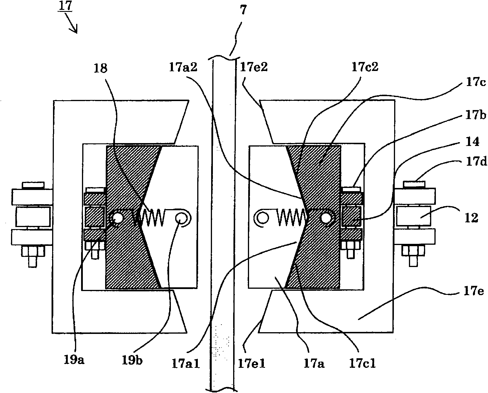
[0052] Such as figure 2 and image 3 As shown, the brake device 10 of this embodiment has: brake arms 12, which are arranged in pairs in an opposing manner, and are arranged to be able to rotate through the shaft 11; brake elastic bodies 13, which are sandwiched Between the braking arms 12; the workin...


PUM


Abstract

The invention provides a brake device for an elevator capable of respectively arranging an elastomer for work and an elastomer for brake into independent structures and preventing the counterforce generated during brake having bad effect on other devices. The brake device comprises: brake arms arranged in pair and capable of rotating; an elastomer for brake clamped between brake arms; a work arm arranged at the inner side of the brake arm and in pairs and capable of rotating; an elastomer for work and an actuator clamped between the work arms; a brake part arranged at the end of the brake arm and the work arm, wherein the brake part comprises a brake piece moving under the function of the friction force generated during pressing brake piece on a guide rail; an inclined body for work supported by the end of the work arm; an inclined body for brake supported by the end of the brake arm; an elastomer for reset clamped between the brake piece and the inclined body for work, after braking, the elastomer for reset resets the brake piece in the neutral position.

Description

technical field [0001] The present invention relates to a braking device for an elevator, in particular to a braking device for an elevator that uses an actuator to brake the lifting body when the lifting speed exceeds a specified value or when the lifting body moves in an uncontrolled state. Braking device. Background technique [0002] Among the known brake devices that use actuators to brake lifting bodies, there are, for example, the following brake devices, which have an actuator and a brake member, and the actuator has a working force capable of overcoming the elastic force , and its power supply will be disconnected under specified conditions. When the power supply of the actuator is disconnected, the braking member will slide in contact with the guide rail under the action of elastic force, so that the lifting body will decelerate and stop. In addition, a similar brake device using an actuator can also be cited as a brake device that brakes the lifting body when the...

Claims


Application Information

Patent Timeline
Patent Type & Authority Applications(China)
IPC IPC(8): B66B5/18
Inventor 羽田诚秀座间秀隆平野薰酒井悠至
Owner HITACHI LTD
Why Eureka
Try Eureka