Multi-frequency oscillator applied to electronic ballast

A multi-frequency and oscillator technology, applied in the field of frequency oscillators and analog integrated circuits, can solve the problems of fixed oscillator frequency, shortened life of fluorescent lamps, inability to complete preheating and ignition of fluorescent lamps, etc., to prolong life, meet preheating and The effect of ignition

Inactive Publication Date: 2010-11-03
XIDIAN UNIV
View PDF4 Cites 20 Cited by
  • Summary
  • Abstract
  • Description
  • Claims
  • Application Information

AI Technical Summary

Problems solved by technology

[0004] It can be seen that, because the above-mentioned existing oscillator charge and discharge current is constant, the frequency of the oscillator is fixed, and the preheating and ignition of the fluorescent lamp cannot be completed, resulting in shortened life of the fluorescent lamp.

Method used


Image

  • Multi-frequency oscillator applied to electronic ballast
  • Multi-frequency oscillator applied to electronic ballast
  • Multi-frequency oscillator applied to electronic ballast

Examples


Embodiment Construction

[0021] The present invention will be described in further detail below with reference to the accompanying drawings.

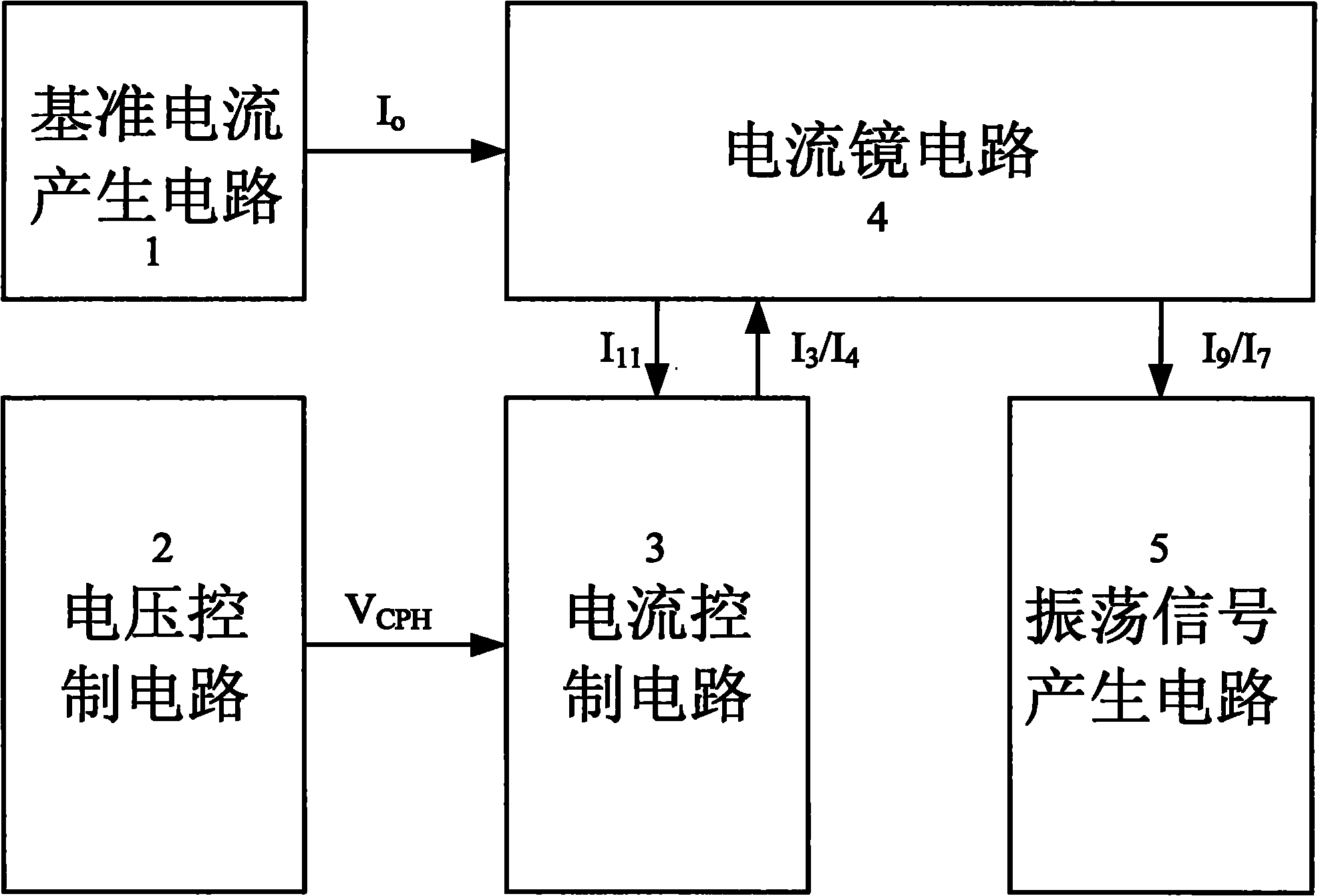
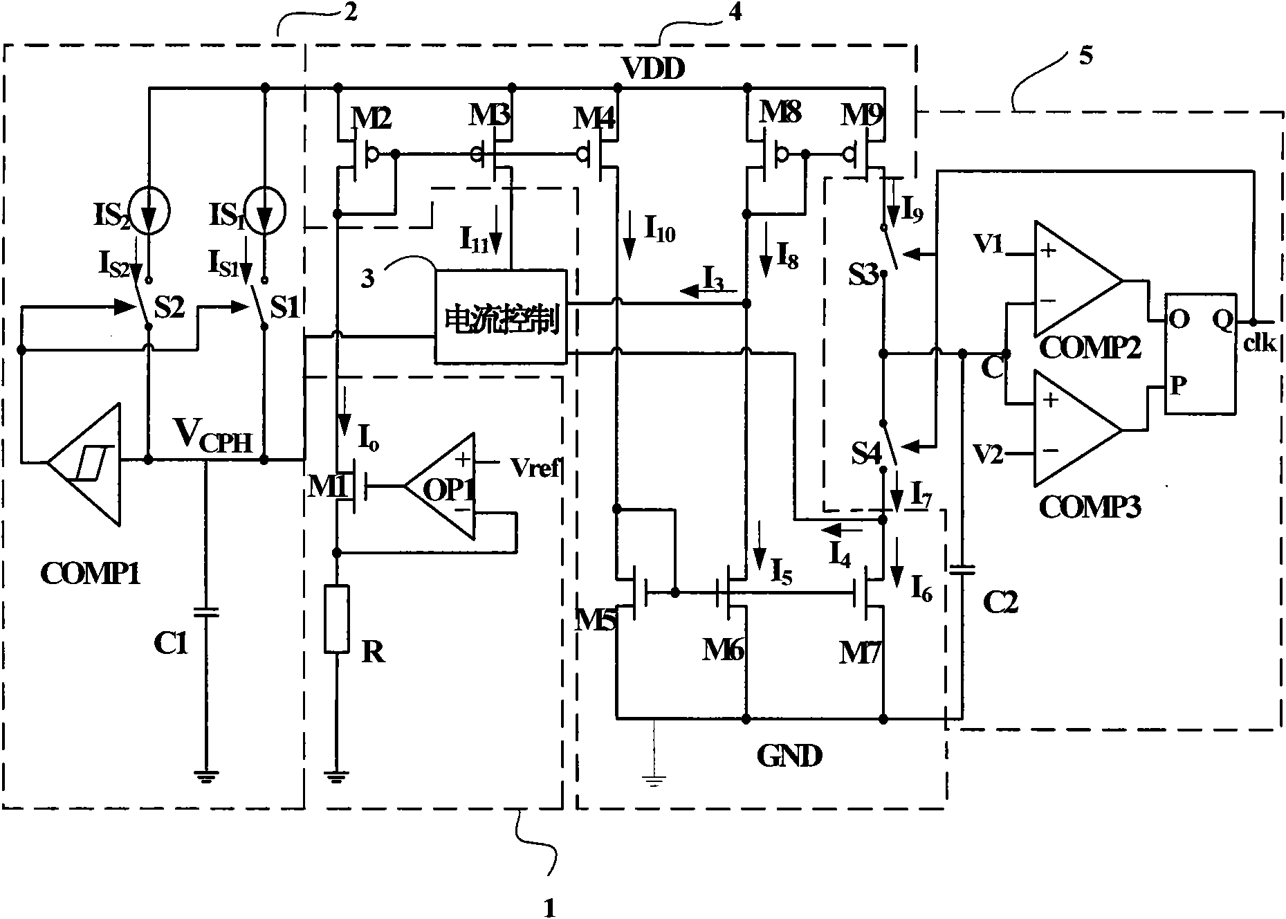
[0022] refer to figure 2 , the multi-frequency oscillator of the present invention mainly includes a reference current generation circuit 1 , a voltage control circuit 2 , a current control circuit 3 , a current mirror circuit 4 and an oscillation signal generation circuit 5 . in:

[0023] A reference current generating circuit 1, which generates a reference current I that is a function of the reference voltage o Input to current mirror circuit 4, which outputs current I 11 To the current control circuit 3, the current control circuit simultaneously passes the output voltage V of the voltage control circuit 2 CPH control, output two currents I 3 / I 4 Return to the current mirror circuit 4, so that the current mirror circuit generates two charging and discharging currents I 9 / I 7 Output to the oscillation signal generating circuit 5 .

[0024] refer to...


PUM


Abstract

The invention discloses a multi-frequency oscillator applied to an electronic ballast, which mainly solves the problems that a fluorescent lamp has no preheating or ignition and has short service life. The multi-frequency oscillator of the invention comprises a reference current generating circuit, a voltage control circuit, a current control circuit, a current mirror circuit and an oscillating signal generating circuit, wherein the current control circuit is connected between the reference current generating circuit and the current mirror circuit to generate charge/discharge current in a functional relationship with reference current and voltage control output voltage so that the oscillator works in different frequencies; the voltage control circuit is connected on the output of the current control circuit; and the current control circuit is controlled by the output of the voltage control circuit so as to realize adjustment of different frequency time of the oscillator and finish preheating, ignition and normal light emission of the fluorescent lamp. The multi-frequency oscillator can prolong the service life of the fluorescent lamp, and can be widely applied to the electronic ballast of the fluorescent lamp.

Description

technical field [0001] The invention belongs to the technical field of electronic circuits, and relates to an analog integrated circuit, in particular to a frequency oscillator, which can be used in an electronic ballast for fluorescent lamps. Background technique [0002] Multi-frequency oscillators are widely used in electronic ballasts of fluorescent lamps, and can complete the preheating, start-up and normal lighting of fluorescent lamps by changing their frequencies in different time periods. According to the characteristics of the preheating fluorescent lamp, its normal operation needs to have three working stages: 1. Give a large current to the filament for preheating within a certain period of time; 2. Give the lamp a high enough starting voltage for ignition in a short period of time 3. Finally, make the lamp work normally under rated power. When the lamp circuit is at the preheat frequency f ph Preheat when the frequency is gradually reduced and approach the natu...

Claims


Application Information

Patent Timeline
Patent Type & Authority Applications(China)
IPC IPC(8): H03B5/04H05B41/295H05B41/36
Inventor 来新泉史凌峰何惠森赵永瑞王强王光
Owner XIDIAN UNIV
Why Eureka
Try Eureka