Energy-saving and environment-friendly printer

An energy-saving and environmental-friendly printing machine technology, which is applied to printing machines, printing, general-purpose parts of printing machinery, etc., can solve the problems of low heat utilization efficiency, reduced processing efficiency, and high production consumption, so as to reduce external heat dissipation of equipment and occupy an area of ​​equipment Effects of area reduction and reduction in installation and transportation costs

Inactive Publication Date: 2010-05-05
VERBOCA ENERGY SAVING TECH CO LTD
View PDF2 Cites 10 Cited by
  • Summary
  • Abstract
  • Description
  • Claims
  • Application Information

AI Technical Summary

Problems solved by technology

However, this improvement scheme still has the following problems: 1. In order to control the cost of the device, the waste gas flow rate needs to be reduced, resulting in a more prominent explosion hazard; 2. In the process of waste gas treatment, a huge amount of additional energy is consumed, and the operating cost is high; 3. Activated carbon or activated carbon fiber is a consumable, which needs to be replaced regularly, resulting in an increase in cost and affecting production; 4. The desorption process will cause water pollution; the equipment is complex and bulky, occupying more valuable production sites, and causing more damage to the renovation project. 5. It does not help to improve product quality and avoid environmental impact on the production process
[0012] However, an in-depth analysis of the patent document found that the provided equipment has a complex structure, low energy utilization efficiency, lack of good cooperation with processing equipment, high equipment costs and operating costs, making the patent document lack of practicability
[0013] To sum up, the current drying equipment has the following disadvantages: 1. The drying gas enters and exits at the same time, which is difficult to meet the drying process requirements
2. The air blowing stroke is short, the air flow is small, the drying efficiency is low, the box is too long, and the control is difficult
3. Low heat utilization efficiency, excessive energy consumption and high operating costs
4. The air duct is complex and has many interfaces, the gas is easy to leak, the fan noise is loud, and the environmental protection is poor
5. The structure is complex, bulky, consumes a lot of steel, and the manufacturing cost is high
6. It is troublesome to install and transport, the cost is high, and it takes up a lot of space in the factory building
7. Organic solvents are harmful to the human body and the environment, and direct discharge will cause pollution
8. There are extremely economically valuable organic solvents and a large amount of heat in the exhaust gas, which cannot turn waste into treasure, resulting in high production consumption and reduced processing efficiency
9. In order to reduce the energy consumption of heating air, it is necessary to reduce the flow of fresh air, but it will cause the concentration of organic vapor to exceed the explosion limit and cause an explosion accident, which poses a serious safety hazard
10. A large amount of natural air is used, which makes the processing and production subject to the climate environment. When the ambient temperature is low, the energy consumption required for heating is huge, and even the drying needs cannot be met, resulting in production shutdown
11. The dust in the natural air affects the processing quality of the product

Method used


Image

  • Energy-saving and environment-friendly printer
  • Energy-saving and environment-friendly printer
  • Energy-saving and environment-friendly printer

Examples


specific Embodiment

[0048] Figure 1 to Figure 12 Constitute a specific embodiment of the present invention.

[0049] This embodiment is a solvent gravure printing machine.

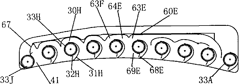
[0050] in, Figure 1 to Figure 8 The detailed structure of the drying device used in this embodiment is provided, Figure 9 A schematic diagram of the heat pump device used in the drying device of this embodiment is provided.

example

[0052] The corresponding relationship between component names and reference signs in each drawing is shown in Table 1.

[0053] Table 1: Correspondence between part names and reference signs

[0054]

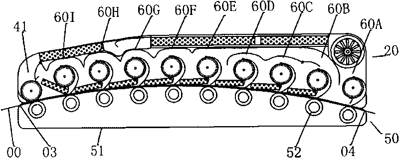
[0055] Such as figure 1 , figure 2 As shown, the drying device 10 includes an oven cover 20 , a base 50 , and is provided with a printed product inlet 03 and a printed product outlet 04 .

[0056] The base 50 includes a base housing 51 and support rollers 52 . The printed product 00 enters from the printed product inlet 03 , is blown by the air blowing unit 60 under the support of the support roller, and leaves the drying device 10 through the printed product outlet 04 after drying.

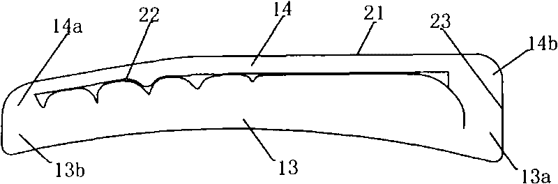
[0057] Oven lid 20 comprises outer cover part 21, partition part 22, frame part 23, nine air supply units 60A~60I, a circulation unit 41, is provided with drying chamber 13, recovery chamber 14; Drying chamber 13 is made up of partition part 22. The frame part 23 is surrounded by the base ...


PUM


Abstract

The invention relates to an energy-saving and environment-friendly printer, comprising a printer body and a drying device (10). The energy-saving and environment-friendly printer is characterized in that the drying device (10) comprises an oven cap (20) and a base (50), and is provided with a printing product inlet (03) and a printing product outlet (04); the oven cap (20) is provided with a drying cavity (13) and a recovering cavity (14); an air supply unit (60), a heat pump condenser (88) and a refrigerating evaporator (96) are arranged in the oven cap (20); the air supply unit (60) comprises a fan (30) provided with an air inlet channel (63), an air exhaust channel (64) and an air outlet channel (68) to form an air blowing and circulating system; the heat pump condenser (88) is installed in the air supply unit (60), and the refrigerating evaporator (96) is installed in the recovering cavity (14). In the invention, drying equipment is firstly reformed, and an air channel with skillful interior is utilized to replace the original air channel with complicated structure and signal function, thereby the effects of compact structure, space saving and reduction of material consumption are achieved.

Description

technical field [0001] The invention relates to a printing machine, in particular to an energy-saving and environment-friendly printing machine. It belongs to the field of printing technology. Background technique [0002] At present, packaging printed matter is generally in the form of a roll, and is usually printed continuously by gravure printing machine or flexo printing machine. The printed matter needs to be preheated before printing, printed matter needs to be dried during the printing process, and printed matter needs to be cooled after printing. [0003] The current printing machine, including gravure and flexo, is dried by hot air blowing, that is, the air is heated and then blown to achieve the purpose of drying the printed product, and the preheating is completed in a similar way to drying. Cooling is mostly done with chill rolls. [0004] The preheating, drying, and cooling of current printing machines all have the disadvantages of complex structure, large vol...

Claims


Application Information

Patent Timeline
Patent Type & Authority Applications(China)
IPC IPC(8): B41F23/04
Inventor 简甦
Owner VERBOCA ENERGY SAVING TECH CO LTD
Why Eureka
Try Eureka