System for protecting optical link of passive optical network, device thereof and method thereof

A passive optical network and optical link technology, applied in the selection device, transmission system, selection device and other directions of the multiplexing system, can solve the problem that the implementation method is not given, and the robustness and practicability of the protection system are not further to discuss and other issues to achieve the effect of avoiding switching

Active Publication Date: 2010-11-03
ZTE CORP
View PDF2 Cites 31 Cited by
  • Summary
  • Abstract
  • Description
  • Claims
  • Application Information

AI Technical Summary

Problems solved by technology

The protocol only briefly describes the physical model, and provides the definition of the extended Operation Administration Maintenance (OAM, Operation Administration Maintenance) frame format for simple...

Method used


Image

  • System for protecting optical link of passive optical network, device thereof and method thereof
  • System for protecting optical link of passive optical network, device thereof and method thereof
  • System for protecting optical link of passive optical network, device thereof and method thereof

Examples


Embodiment Construction

[0058] The technical solutions of the present invention will be described in detail below in conjunction with the accompanying drawings and preferred embodiments. The following examples are only used to illustrate and explain the present invention, but not to limit the technical solution of the present invention.

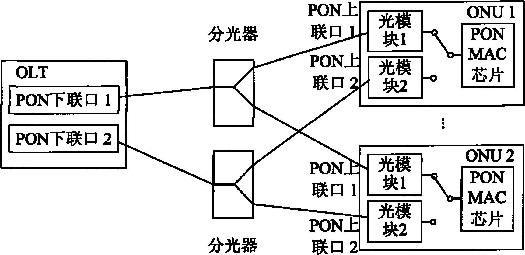
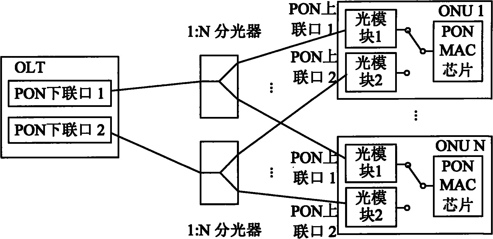
[0059] Such as figure 1 Shown is the networking structure of an embodiment of the system for realizing passive optical network optical link protection provided by the present invention. The system includes an optical line terminal (OLT), two optical splitters and two optical network units (ONUs). ),in:

[0060] The OLT is used to connect to two optical splitters through two downlink ports (PON downlink port 1 and PON downlink port 2);

[0061] The optical splitter is used to divide the optical link from one downlink port of the OLT into two optical links, and each optical link is connected to one uplink port of two ONUs respectively;

[0062] The ONU is used to c...


PUM


Abstract

The invention discloses a system for protecting an optical link of a passive optical network, a device thereof and a method thereof. The system comprises an optical line terminal, two optical splitters and a plurality of optical network units, wherein the optical line terminal is respectively connected with the two optical splitters through two lower connecting ports; the optical splitters the optical link which is from one lower connection port of the optical line terminal into a plurality of optical links; the plurality of optical network units respectively and correspondingly connect two upper connecting ports with one optical link on the two optical splitters; the mutually-protected optical links are formed between the optical line terminal and the two optical splitters; and the mutually-protected optical links are formed between each optical splitter and every two optical network units. By fast detecting the optical link, the invention effectively filters the dither of an optical signal on the optical link caused by the noise, the fault and the manual unplugging and plugging, thereby being capable of preventing from frequently switching between the two mutually-protected optical links.

Description

technical field [0001] The invention relates to optical fiber access technology, in particular to a method, system and device for protecting optical fibers of a passive optical network (PON, Passive Optical Network). Background technique [0002] Ethernet passive optical network is a new type of optical fiber access network technology, which adopts point-to-multipoint structure and passive optical fiber transmission, and provides various services on Ethernet. It adopts PON technology in the physical layer, uses Ethernet protocol in the link layer, and realizes the access of Ethernet by using the topological structure of PON. Therefore, it combines the advantages of PON technology and Ethernet technology: low cost, high bandwidth, strong scalability, flexible and fast service reorganization, compatibility with existing Ethernet, and convenient management. [0003] In recent years, the user scale of the access network has continued to expand, and the requirements for network ...

Claims


Application Information

Patent Timeline
IPC IPC(8): H04B10/08H04B1/74H04L12/24H04L12/26H04B10/032
CPCH04Q2011/0081H04Q11/0067H04B10/032
Inventor 马兴睿刘少情王欣张海军
Owner ZTE CORP
Why Eureka
Try Eureka