Non-isolated AC-DC (Alternating Current-Direct Current) LED driver current compensation circuit

A current compensation circuit, non-isolated technology, applied in the direction of lamp circuit layout, electric light source, irreversible AC power input conversion to DC power output, etc.

Active Publication Date: 2010-11-03
CRM ICBG (WUXI) CO LTD
View PDF2 Cites 27 Cited by
  • Summary
  • Abstract
  • Description
  • Claims
  • Application Information

AI Technical Summary

Problems solved by technology

For such a peak current control method, even if the input grid voltage does not c

Method used


Image

  • Non-isolated AC-DC (Alternating Current-Direct Current) LED driver current compensation circuit
  • Non-isolated AC-DC (Alternating Current-Direct Current) LED driver current compensation circuit
  • Non-isolated AC-DC (Alternating Current-Direct Current) LED driver current compensation circuit

Examples


Embodiment Construction

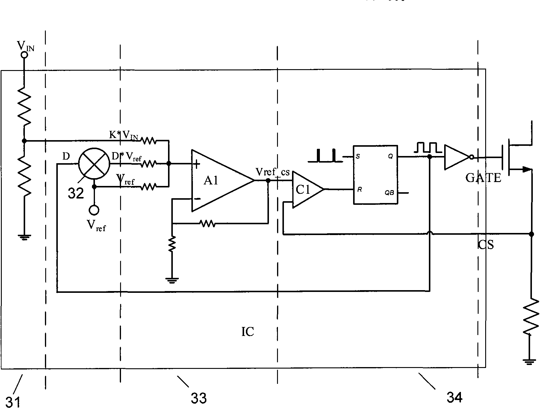
[0017] image 3 It is a schematic circuit diagram of the peak current compensation adopted in the present invention.

[0018] The circuit includes an input voltage detection circuit 31, a duty cycle detection circuit 32, an addition circuit 33 and a control circuit 34. Figure 5-7 The specific composition of each circuit is given in .

[0019] Figure 5 Yes image 3 In the circuit diagram of the input voltage detection circuit in , a resistance network is formed by connecting resistors R51 and R52 in series. By selecting a suitable ratio of resistance values, the input voltage detection circuit 31 generates k*V in signal to meet the voltage required for detection, the obtained input voltage change signal k*V in Will and V ref Added in the addition circuit 33 to control the reference of the peak current to increase with the increase of the input voltage.

[0020] Image 6 Yes image 3 The specific circuit diagram of the medium duty ratio detection circuit, the detection...


PUM


Abstract

The invention relates to a non-isolated AC-DC (Alternating Current-Direct Current) LED driver peak current compensation method. The method ensures that an LED driver controlled by peak current can maintain constant LED current within different input voltage ranges and on the condition of driving different quantities of LEDs, and then the brightness of the LEDs is remained unchanged. On the basis of peak current control, a current peak is compensated according to input voltage and the quantity of output LEDs so as to ensure that average current flowing through the LEDs maintains constant.

Description

technical field [0001] The invention relates to an LED driver current compensation circuit, in particular to a non-isolated AC-DC LED driver current compensation circuit. Background technique [0002] In the application of high voltage input, a buck converter is usually used to drive the LED to make the output current constant, and it is hoped that the output current will be constant under different input voltage V IN and different LED output voltages to get a constant LED current. Since the input voltage is as high as hundreds of volts, the control of the power transistor 16 and the sampling of the current 14 are limited. figure 1 It is a circuit diagram of a commonly used step-down regulator, including a start-up drop-down resistor 10, an input filter capacitor 11, a control chip 13, a frequency setting resistor 15, a diode 18, a power MOS tube 16, an inductor 17, a sampling resistor 14, And LED load 19 and output filter capacitor 20. This circuit uses a peak current co...

Claims


Application Information

Patent Timeline
IPC IPC(8): H05B37/00H05B37/02H02M7/23
Inventor 胡黎强王磊黄家乐关彦青
Owner CRM ICBG (WUXI) CO LTD
Why Eureka
Try Eureka