Method for recovering flue gas waste heat of aluminum electrolysis cell

An aluminum electrolytic cell and flue gas waste heat technology, applied in the field of heat energy recovery devices, can solve the problems of large longitudinal depth, poor resistance on both sides of the purification system, large structure, etc. Low resistance effect

Active Publication Date: 2013-01-02
厦门热工环保系统工程有限公司
View PDF0 Cites 0 Cited by
  • Summary
  • Abstract
  • Description
  • Claims
  • Application Information

AI Technical Summary

Problems solved by technology

[0002] In the aluminum electrolysis industry, there are few projects that recover waste heat from flue gas from aluminum electrolytic cells. figure 2 As shown, one or several waste heat recovery devices 7 are arranged on the main pipe 5 or dry pipe 4 of the aluminum electrolytic cell 1 to meet the heat load demand, and the flue gas passing through the waste heat recovery devices 7 is finally discharged by the induced draft fan 6. This design scheme has the following defects: ① It is impossible to maintain the pressure balance of the exhaust duct system of the original aluminum electrolytic cell 1: due to the newly added waste heat recovery device, the resistance and pressure loss are concentrated on a main pipe 5, resulting in poor resistance on both sides of the purification system , the resistance difference is not only the resistance produced by the newly added waste heat recovery device, but also the resistance caused by various reasons (such as waste heat recovery device dust accumulation) during operation. Therefore, the pressure imbalance of the exhaust purification system on both sides not only affects The waste heat recovery rate has been improved, and there are potential safety hazards; ②The side resistance of the waste heat recovery device in this scheme is relatively large, and it is impossible to use only the operating margin of the induced draft fan 6 that has been put into operation, and it is necessary to install and open additional induced draft fans 6. Increase investment in production equipment; ③The flue gas of aluminum electrolytic cell 1 is a high-dust flue gas, ensuring that the waste heat recovery device 7 is convenient and efficient for dust removal and dust removal, which is the fundamental guarantee for the effective operation of the system. 7 has a large vertical depth and a huge structure, and it is extremely inconvenient to remove dust and dust, and it is impossible to realize online start-up inspection at any time to find hidden dangers in advance; The flue gas waste heat recovery system of electrolytic cell 1 cannot operate normally, and the aluminum electrolytic cell 1 of the process production equipment cannot operate normally
⑤ It cannot be guaranteed that the temperature difference between the flue gas in the waste heat recovery device and the heated liquid (that is, the hot and cold fluid in the waste heat recovery device) reaches the reasonable value range for practical engineering applications

Method used


Image

  • Method for recovering flue gas waste heat of aluminum electrolysis cell
  • Method for recovering flue gas waste heat of aluminum electrolysis cell

Examples


Embodiment Construction

[0010] Now illustrate the present invention in conjunction with accompanying drawing and embodiment.

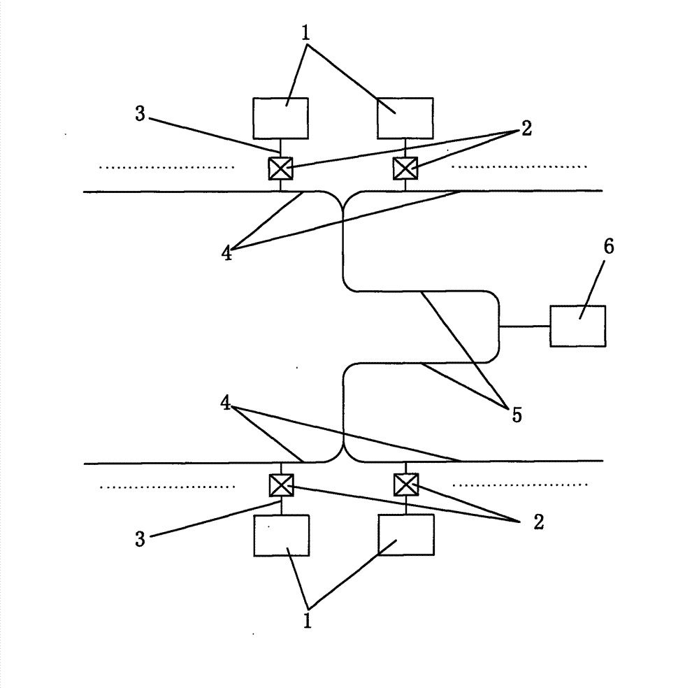
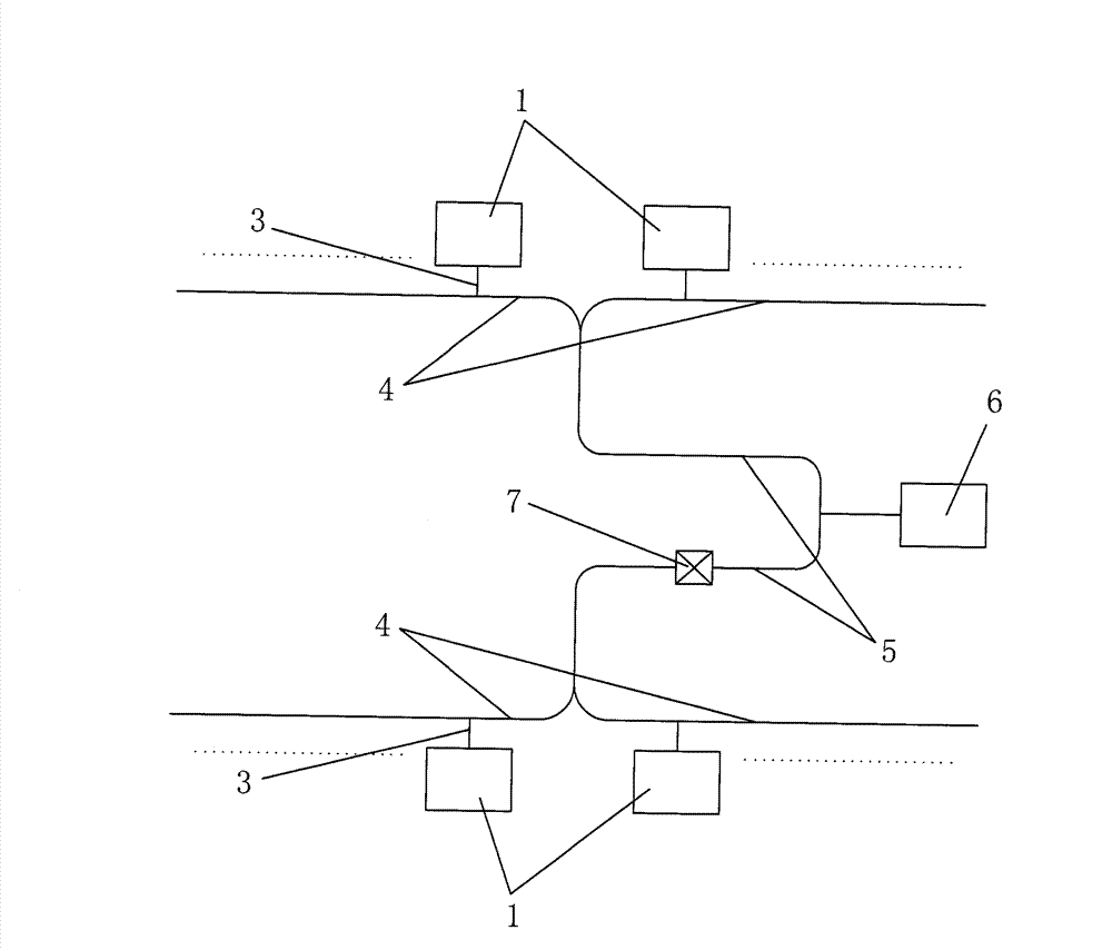
[0011] Such as figure 1 In the shown method for recovering waste heat from flue gas from an aluminum electrolytic cell, the flue gas discharged from an aluminum electrolytic cell 1 sequentially passes through a smoke exhaust branch pipe 3, a smoke exhaust main pipe 4, and a smoke exhaust main pipe 5, and finally is discharged through an induced draft fan 6. The present invention A waste heat recoverer 2 for recovering the flue gas directly discharged from the aluminum electrolytic cell 1 is installed on the exhaust branch pipe 3 of each aluminum electrolytic cell 1 , and each waste heat recovery device 2 corresponds to one aluminum electrolytic cell 1 . Every additional waste heat recovery device 2 is installed on the smoke exhaust branch pipe 3 of the aluminum electrolytic cell 1 that is the closest to the pipeline distance of the induced draft fan. The arrangement of the ...


PUM


Abstract

The invention discloses a method for recovering flue gas waste heat of an aluminum electrolysis cell. A waste heat recoverer is arranged on an exhaust branch pipe of the aluminum electrolysis cell. Compared with the prior art, the invention adopts a technical scheme that the waste heat recoverer is in axial symmetry vertically and horizontally, or the flue gas side resistance value generated by the waste heat recoverer is increased or decreased, so that the exhaust pressure difference of an exhaust main pipe on the point of vertically axial symmetry is zero. The exhaust pressure difference ofthe exhaust main pipe on the point of vertically axial symmetry is zero, so the problem of imbalanced pressure caused by arranging a waste heat recovery system in the exhaust air pipe system of the aluminum electrolysis cell in the prior art is solved. The single waste heat recoverer has small flue gas side resistance, sufficiently utilizes the pressure surplus value in the system without increasing the number of a draught fan, and has the advantages of small depth, convenient ash cleaning and dust removal, and high efficiency. Every waste heat recoverer is a relatively independent system, and can be inspected and maintained on-line at all times, so that hidden dangers can be discovered in advance to ensure safe production.

Description

technical field [0001] The invention relates to a heat energy recovery device, which is especially suitable for the waste heat recovery of flue gas from an aluminum electrolytic cell, and utilizes the waste heat of the aluminum electrolytic cell to save energy consumption and reduce emissions. Background technique [0002] In the aluminum electrolysis industry, there are few projects that recover waste heat from flue gas from aluminum electrolytic cells. figure 2 As shown, one or several waste heat recovery devices 7 are arranged on the main pipe 5 or dry pipe 4 of the aluminum electrolytic cell 1 to meet the heat load demand, and the flue gas passing through the waste heat recovery devices 7 is finally discharged by the induced draft fan 6. This design scheme has the following defects: ① It is impossible to maintain the pressure balance of the exhaust duct system of the original aluminum electrolytic cell 1: due to the newly added waste heat recovery device, the resistance ...

Claims


Application Information

Patent Timeline
Patent Type & Authority Patents(China)
IPC IPC(8): C25C3/22
Inventor 杨煜
Owner 厦门热工环保系统工程有限公司
Why Eureka
Try Eureka