Eureka AIR delivers breakthrough ideas for toughest innovation challenges, trusted by R&D personnel around the world.

Synchronous end seal remover

A terminal and U-shaped technology, applied in the field of end seal removal tools, can solve the problems of waste, track plate damage, low efficiency, etc., and achieve the effect of simple structure and reasonable operation

Active Publication Date: 2010-11-10
CHINA RAILWAY FIRST GRP CO LTD
View PDF6 Cites 0 Cited by
  • Summary
  • Abstract
  • Description
  • Claims
  • Application Information

AI Technical Summary

Problems solved by technology

[0002] After the track slab is poured with concrete, it is necessary to remove the end seal of the track slab. The existing method of removing the end seal is manual knocking. Using this method is likely to cause asynchronous exit when the end seal is removed, and knocking It is easy to touch the horizontal edge of the bottom surface of the track plate, causing certain damage to the track plate. In addition, using a hammer to strike will cause loss and deformation of the end seal. The disassembled end seal cannot be reused, causing a lot of waste, and this A method of manual tapping is less efficient

Method used


Image

  • Synchronous end seal remover
  • Synchronous end seal remover
  • Synchronous end seal remover

Examples


Embodiment Construction

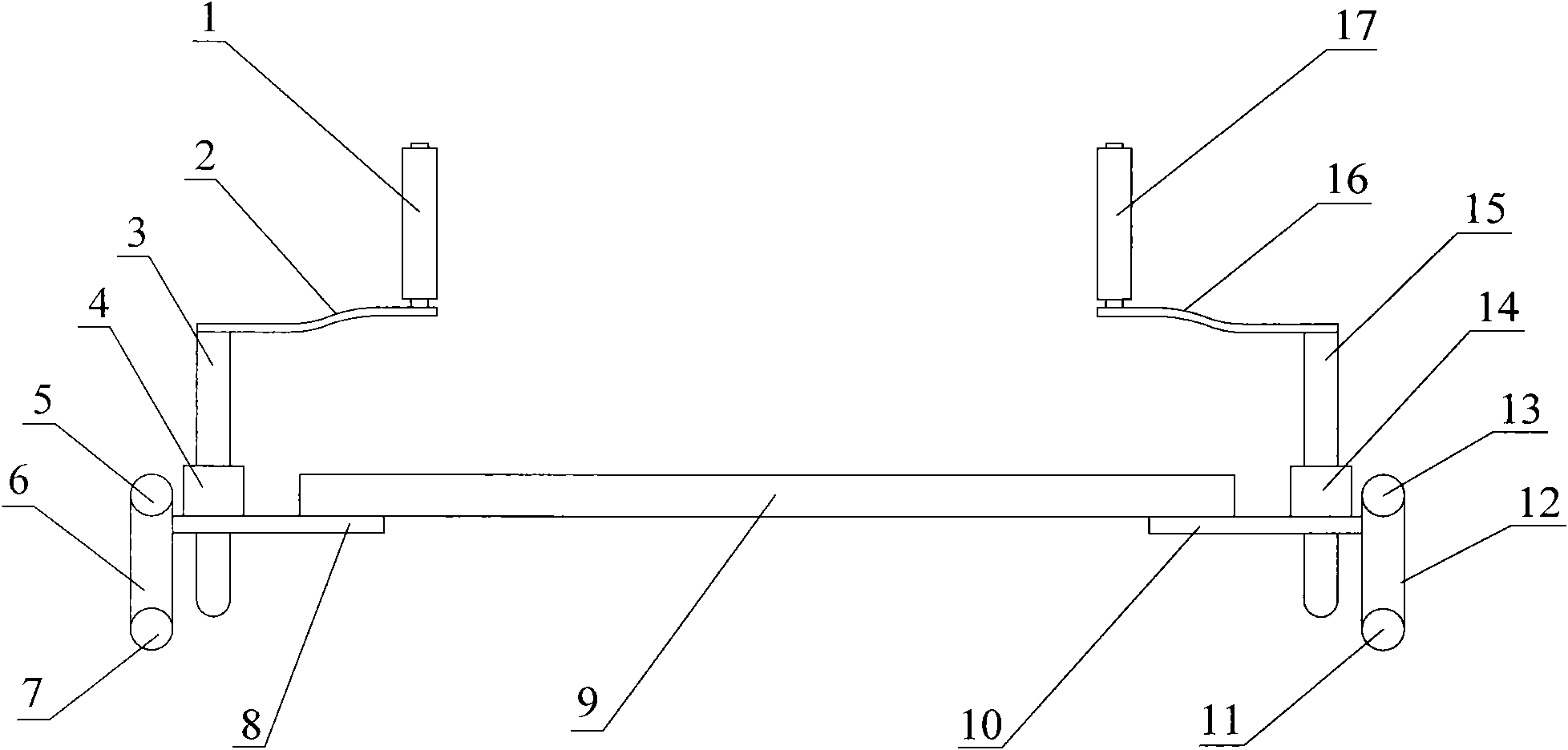
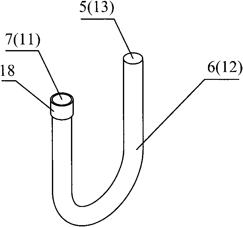
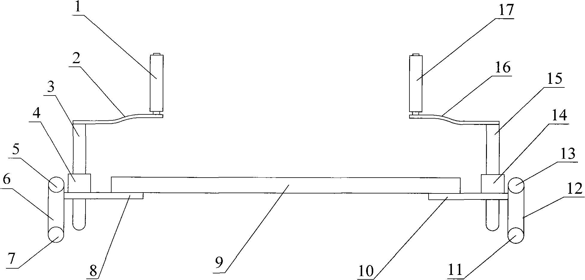
[0022] Such as figure 1 The shown synchronous end seal remover includes U-shaped component 1 6, U-shaped component 2 12, base plate 1 8, base plate 2 10, screw 1 3, screw 2 15, connecting rod 1 2, connecting rod 2 16, Crank 1, crank 2 17, nut 1 4, nut 2 14 and connecting rod 3 8; the U-shaped member 1 6 and U-shaped member 2 12 adopt U-shaped threaded steel, and the base plate 8 and base plate 10 adopt steel plates , the U-shaped component 6 is installed on the base plate 8, the nut 4 is located on one side of the U-shaped component 6 and fixed on the base plate 8, and the screw rod 3 is sleeved in the nut 4 and passed through Through the base plate one 8, the screw rod one 3 is connected with the crank handle one 1 through the connecting rod one 2; the U-shaped component two 12 is installed on the base plate two 10, the screw rod two 15 is located on the side of the U-shaped component two 12 and Fixed on the base plate 2 10, the screw rod 2 15 is sleeved in the nut 2 14 and ...


PUM


Abstract

The invention discloses a synchronous end seal remover which comprises a U-shaped member (1), a U-shaped member (2), a substrate (1), a substrate (2), a screw rod (1), a screw rod (2), a connecting rod (1), a connecting rod (2), a crank handle (1), a crank handle (2), a nut (1), a nut (2) and a connecting rod (3), wherein the U-shaped member (1) is installed on the substrate (1); the nut (1) is positioned at one side of the U-shaped member (1) and fixed on the substrate (1); the screw rod (1) is sleeved in the nut (1) and penetrates through the substrate (1); the screw rod (1) is connected with the crank handle (1) through the connecting rod (1); the U-shaped member (2) is installed on the substrate (2); the screw rod (2) is positioned at one side of the U-shaped member (2) and fixed on the substrate (2); the screw rod (2) is sleeved in the nut (2) and penetrates through the substrate (2); the screw rod (2) is connected with the crank handle (2) through the connecting rod (2); and the substrate (1) and the substrate (2) are connected through the connecting rod (3). The invention has simple and reasonable structure and can be used conveniently, the traditional manual removing method by knocking is changed, and loss and deformation of the end seal can not be caused.

Description

technical field [0001] The invention relates to an end seal removal tool, in particular to a synchronous end seal remover for removing the end seal of a track slab. Background technique [0002] After the track slab is poured with concrete, it is necessary to remove the end seal of the track slab. The existing method of removing the end seal is manual knocking. Using this method is likely to cause asynchronous exit when the end seal is removed, and knocking It is easy to touch the horizontal edge of the bottom surface of the track plate, causing certain damage to the track plate. In addition, using a hammer to strike will cause loss and deformation of the end seal. The disassembled end seal cannot be reused, causing a lot of waste, and this The method efficiency of a kind of artificial percussion is lower. Contents of the invention [0003] The purpose of the present invention is to overcome the shortcomings of the above-mentioned prior art and provide a synchronous end s...

Claims


Application Information

Patent Timeline
Patent Type & Authority Applications(China)
IPC IPC(8): E01B37/00E01B1/00
Inventor 张卫祥王斌闫艳兵白双明李晓
Owner CHINA RAILWAY FIRST GRP CO LTD
Why Eureka
Eureka Blog
Learn More