Prestressed concrete mansard rigid-frame beam

A concrete, polyline-shaped technology, applied in the field of rigid frame beams, can solve problems such as unfavorable earthquake resistance, large inertial force, and self-heavy beam body, and achieve the effect of saving the volume of formwork materials

Active Publication Date: 2010-11-10
白福波
View PDF4 Cites 9 Cited by
  • Summary
  • Abstract
  • Description
  • Claims
  • Application Information

AI Technical Summary

Problems solved by technology

[0003] The purpose of the present invention is to provide a prestressed concrete broken-line rigid frame beam to solve the problem that the existing wide flat beams in high-rise buildings are not conducive to earthquake resistance due to their heavy beam body (large inertial force); the occupied floor height makes indoor energy consumption relative increase in the problem

Method used


Image

  • Prestressed concrete mansard rigid-frame beam
  • Prestressed concrete mansard rigid-frame beam
  • Prestressed concrete mansard rigid-frame beam

Examples


specific Embodiment approach 1

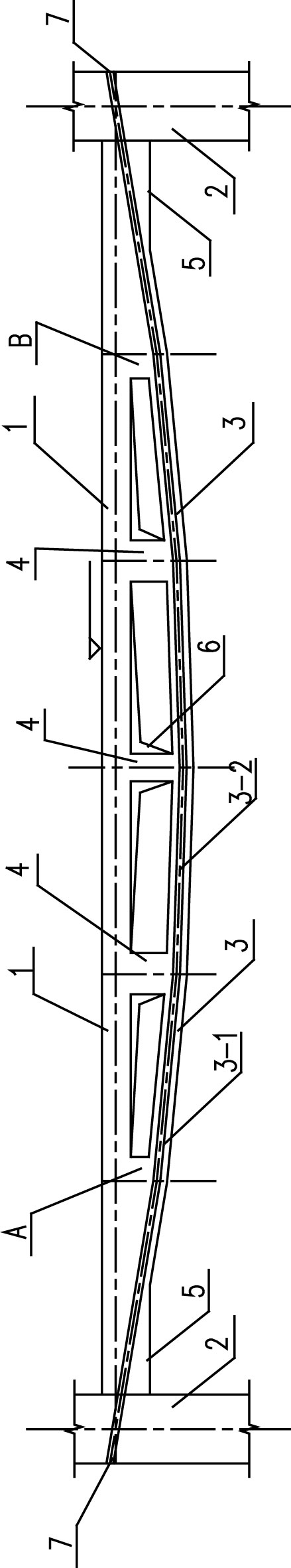
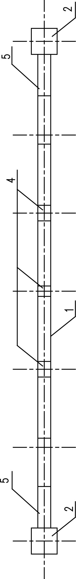
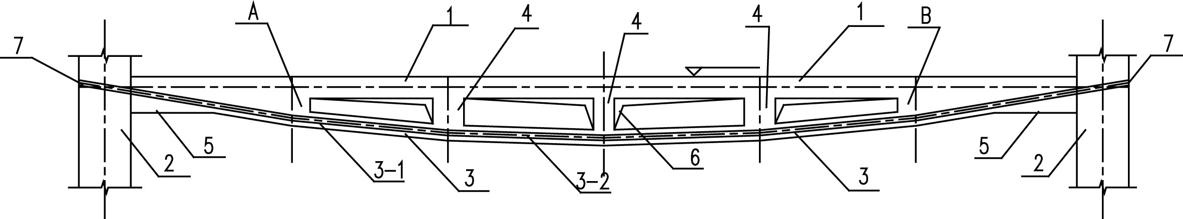
[0009] Specific implementation mode one: as figure 1 As shown, the prestressed concrete broken-line rigid frame beam described in this embodiment includes an upper beam 1 and a plurality of columns 4 with different heights, and the rigid frame beam also includes a lower folded beam 3 and two sections of flat beams 5. The lower folded beam 3 is a beam body formed by connecting a plurality of straight beams 3-1 end-to-end in sequence, and the lower folded beam 3 is located below the upper beam 1, and the outline formed by the two is in an inferior arc shape. , one end of the lower folded beam 3 is rigidly connected to one end of the upper beam 1 to form a first node A, and the other end of the lower folded beam 3 is rigidly connected to the other end of the upper beam 1 to form a second node B, and the upper beam 1 A section of flat beam 5 is respectively arranged at both ends of the two sections of flat beam 5, and one end of one flat section beam 5 in the two sections of flat ...

specific Embodiment approach 2

[0011] Specific implementation mode two: as figure 1 As shown, the cross-sectional area of ​​the flat beam 5 in this embodiment is not less than the sum of the cross-sectional areas of the upper beam 1 and the lower folded beam 3, and the height of the cross-section of the flat beam 5 is not less than that of the upper beam 1 and the lower folded beam 3 The sum of section heights. Guarantee like this that the bearing strength of the flat section beam 5 is not less than other positions. Other components and connections are the same as those in the first embodiment.

specific Embodiment approach 3

[0012] Specific implementation mode three: as figure 1 As shown, the rigid frame beam in this embodiment also includes two frame columns 2, and the other end of one of the two flat section beams 5 is rigidly connected to the inner side wall of one frame column 2, and the two sections of flat section beams 5 are rigidly connected into one body. The other end of the other flat segment beam 5 among the segment beams 5 is rigidly connected to the inner side wall of the other frame column 2 as a whole. The frame column 2 is a commonly used vertical load-bearing member, and connects adjacent span beam ends in the horizontal direction to form continuous multi-span. Other components and connections are the same as those in the second embodiment.


PUM


Abstract

The invention discloses a prestressed concrete mansard rigid-frame beam, which relates to a rigid-frame beam used for floor load bearing and aims to solve the problem that the conventional wide flat beams in high buildings are unfavorable for earthquake resistance due to a large dead weight and occupy floor heights to relatively increase indoor energy consumption. A downwards folded beam is a minor-arc beam formed by connecting a plurality of straight beams and positioned under an upper beam to form a minor-bow outline with the upper beam. One end of a flat beam is rigidly connected with a first joint to form a whole, and one end of another flat beam is rigidly connected with a second joint to form a whole. Between the upper beam and the downwards folded beam, a plurality of upright posts with different heights are arranged and a plurality of holes with different sizes and used for passing electric and water pipelines and small air conditioner pipes through are formed. The downwards folded beam is internally provided with prestressed tendons. Compared with solid beams provided with the prestressed tendons under the same condition and with the uniform cross section, the prestressed concrete mansard rigid-frame beam can reduce the concrete usage and the dead weight by 50 percent and the normal steel bar usage by 25 percent.

Description

technical field [0001] The invention relates to a rigid frame beam used for floor load bearing, in particular to a prestressed concrete broken line rigid frame beam. Background technique [0002] The beam spans widely used in modern buildings are 6 meters to 15 meters. At present, reinforced concrete beams with solid equal section are used as the floor support. The beam height is 0.45 to 1.1 meters, and the beam width is 0.2 to 0.5 meters. Equipment air-conditioning pipelines cross under the beams. In the rooms on each floor of high-rise buildings, in order to save floor height and reduce energy consumption, the optimized floor beams are wide flat beams. When the beam span is 8 meters to 12 meters, the height of the wide flat beam is 0.4 to 0.7 meters, and the width of the wide flat beam is 0.6 to 1.2 meters, and the cumulative amount of materials for each layer is more. Especially in high-rise buildings, the large self-weight (large inertial force) of wide flat beams is...

Claims


Application Information

Patent Timeline
Patent Type & Authority Applications(China)
IPC IPC(8): E04B5/48E04C3/26
Inventor 白福波张小冬梅洪元张煜
Owner 白福波
Why Eureka
Try Eureka