Liquid crystal display

A liquid crystal display and electrode technology, used in static indicators, instruments, electrical digital data processing, etc., can solve the problems of general products without suitable structure, thick liquid crystal display, long process time, etc., to simplify the process and shorten the process. , the effect of improving yield

Inactive Publication Date: 2010-11-10
ACROSENSE TECH
View PDF0 Cites 37 Cited by
  • Summary
  • Abstract
  • Description
  • Claims
  • Application Information

AI Technical Summary

Problems solved by technology

[0002] If a liquid crystal display on a general electronic device needs to have a touch function, a touch panel is installed on the outside of the liquid crystal display for the user to touch or write text as an interface for controlling the operation of the electronic device, but the above-mentioned liquid crystal display The method of manufacturing separately from the touch panel not only makes the thickness of the overall LCD thicker, but also makes the overall process time longer due to two different manufacturing processes
[0003] This shows that above-mentioned existing liquid crystal display obviously still has inconvenience and defect in structure and use, and demands urgently further improving
In order to solve the above-mentioned problems, the relevant manufacturers have tried their best to find a solution, but for a long time no suitable design has been developed, and the general product has no suitable structure to solve the above-mentioned problems. This is obviously the relevant industry. Urgent problem

Method used


Image

  • Liquid crystal display
  • Liquid crystal display
  • Liquid crystal display

Examples


Embodiment Construction

[0040] In order to further explain the technical means and effects of the present invention to achieve the intended purpose of the invention, below in conjunction with the accompanying drawings and preferred embodiments, the liquid crystal display proposed according to the present invention, its specific implementation, structure, features and effects, Details are as follows.

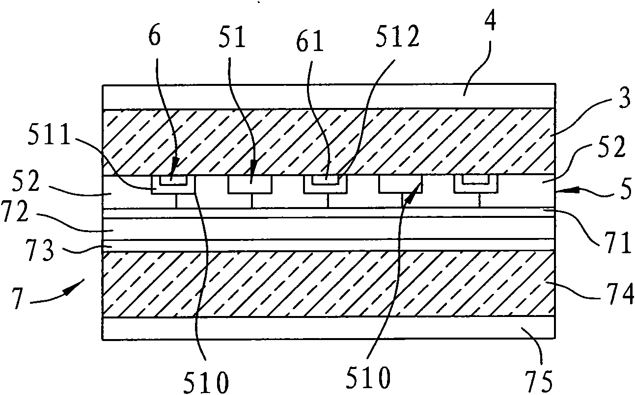
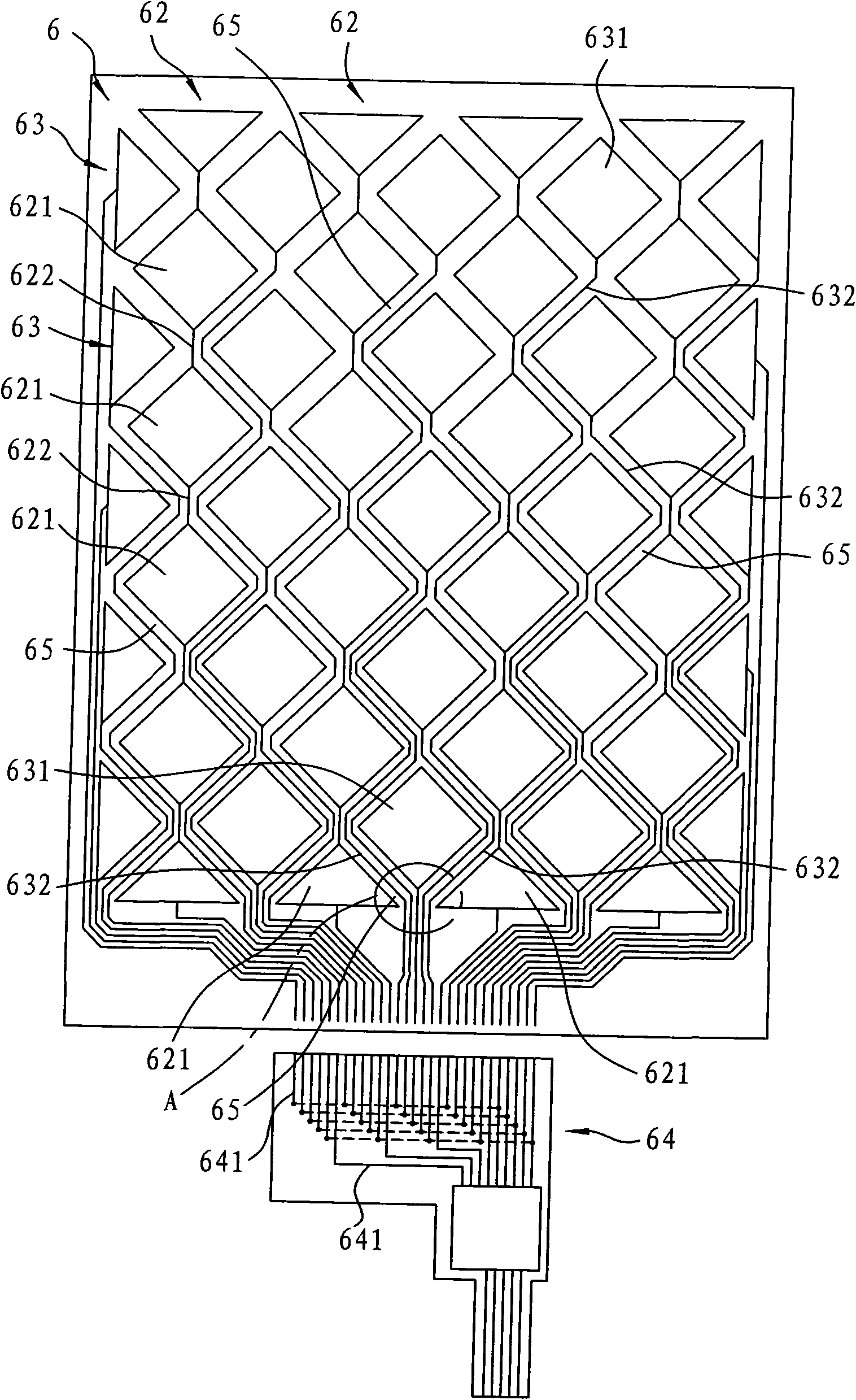
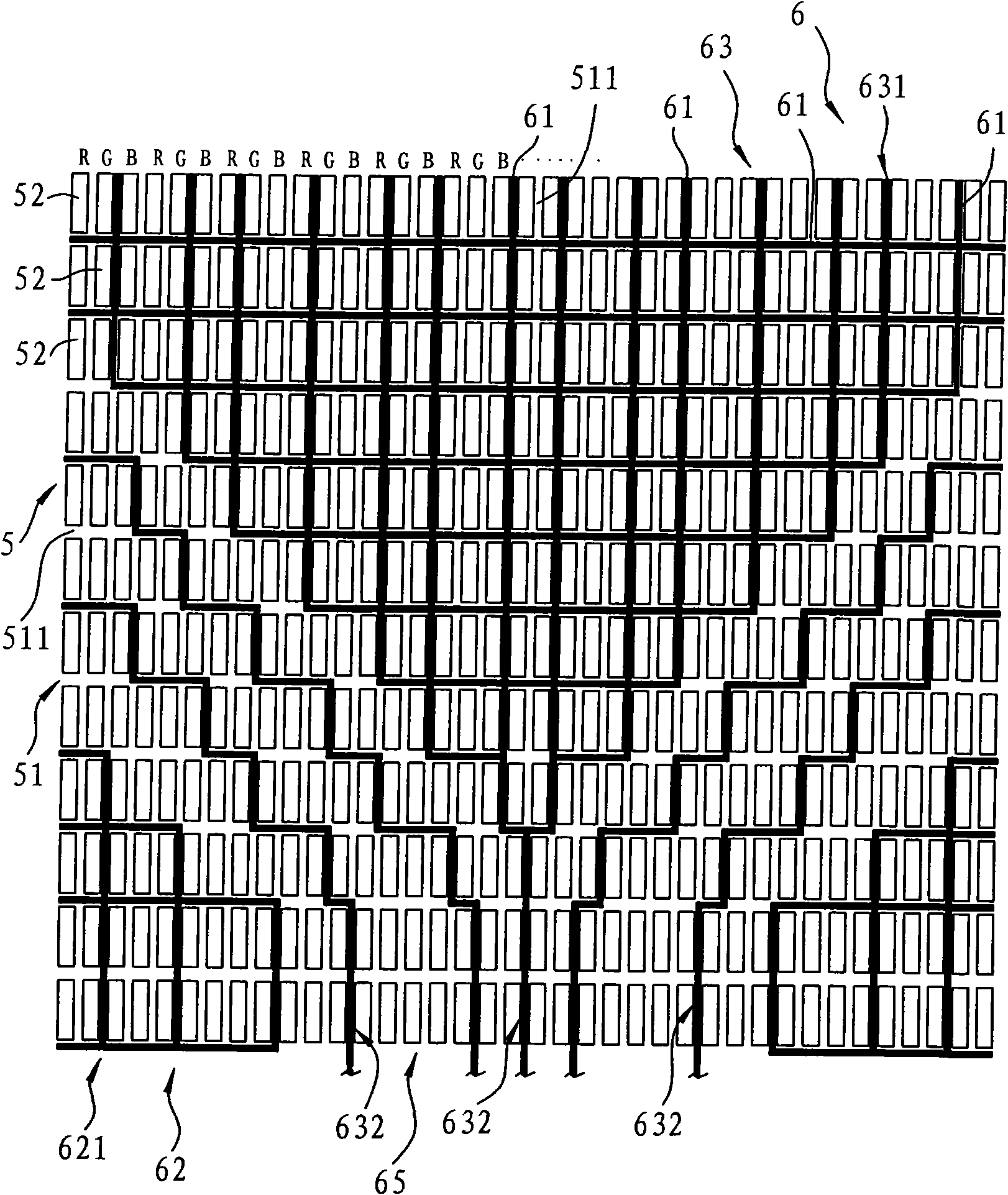
[0041] see figure 1 , figure 2 and image 3 The first preferred embodiment of the liquid crystal display of the present invention comprises a substrate 3, an upper polarizer 4 attached to the top surface of the substrate 3, a color filter unit 5 arranged on the bottom surface of the substrate 3, a color filter unit arranged on the color filter unit 5 is a touch device 6 on the top surface, and a control unit 7 stacked on the bottom surface of the color filter unit 5 .

[0042] The substrate 3 is made of transparent material, and the upper polarizer 4 is pasted on the top surface of the substrate 3. ...


PUM


Abstract

The invention relates to a liquid crystal display, which comprises a base plate, a color light filtering unit and a touch controller, wherein the color light filtering unit is arranged on the bottom surface of the base plate, the touch controller is arranged on the top surface of the color light filtering unit, the color light filtering unit comprises a black matrix frame and a plurality of primary color pixels, a plurality of frame holes are circulated and defined out by the black matrix frame, the primary color pixels are respectively arranged in the frame holes, the touch controller consists of a plurality of conducting wire threads arranged on the black matrix frame, the touch controller comprises a plurality of row electrodes, a plurality of line electrodes, a plurality of row conducting wires electrically connected with the row electrodes, and a plurality of line conducting wires electrically connected with the line electrodes, and in addition, the row conducting wires and the line conducting wires avoid each other, extend at intervals, and are not mutually staggered. The touch controller made of the conducting wire threads is directly formed on the black matrix frame, so the manufacture process can be shortened, and the influence on the output brightness or the image definition of the liquid crystal display caused by the arrangement of the touch controller can also be avoided.

Description

technical field [0001] The invention relates to a liquid crystal display, in particular to a liquid crystal display with a touch function. Background technique [0002] If the liquid crystal display on a general electronic device needs to have a touch function, a touch panel is usually installed on the outside of the liquid crystal display for the user to touch or write text as an interface for controlling the operation of the electronic device, but the above-mentioned liquid crystal display The method of manufacturing separately from the touch panel not only makes the overall thickness of the liquid crystal display thicker, but also makes the overall manufacturing time longer due to two different manufacturing processes. [0003] Thus it can be seen that above-mentioned existing liquid crystal displays obviously still have inconvenience and defects in structure and use, and need to be further improved urgently. In order to solve the above-mentioned problems, the relevant m...

Claims


Application Information

Patent Timeline
Patent Type & Authority Applications(China)
IPC IPC(8): G02F1/133G06F3/041
Inventor 张毅孙正宏张宏荣汤同扬
Owner ACROSENSE TECH
Why Eureka
Try Eureka