Trigger switch with power failure restart protection function

A protection function and trigger technology, which is applied to the power device and electrical components inside the switch, can solve the problems of easy danger, non-conformity, and easy wear, and achieve the effect of low cost, compact structure, and easy maintenance and repair.

Inactive Publication Date: 2010-11-10
ZHEJIANG JIABEN ELECTRONICS CO LTD
View PDF4 Cites 20 Cited by
  • Summary
  • Abstract
  • Description
  • Claims
  • Application Information

AI Technical Summary

Problems solved by technology

In the power-on state, that is, if the power is suddenly cut off during the normal operation of the machine, if the user of the machine forgets to unlock the trigger switch, that is, the switch lock button is decoupled from the casing, the machine is still running when the power is turned on, and the current of this type of switch is relatively large. Used for high-power electric tools, it is extremely dangerous, does not meet the GB3883.7 standard, and poses a major safety hazard to personal life
[0004] 2. The inside of the commonly used trigger switch is a double-pole single-throw structure. Since the switch relies on the spring piece to drive the swing arm of the internal moving contact of the switch to realize the on and off action, this structure determines that the switch cannot be durable. The joints of the head swing arm are prone to wear during the rotation process. When the wear is severe, the switch will heat up rapidly under the power-on state and the switch will be burned. It does not meet the GB15092.1-2003 standard and poses a major safety hazard to human life.

Method used


Image

  • Trigger switch with power failure restart protection function
  • Trigger switch with power failure restart protection function
  • Trigger switch with power failure restart protection function

Examples


Embodiment Construction

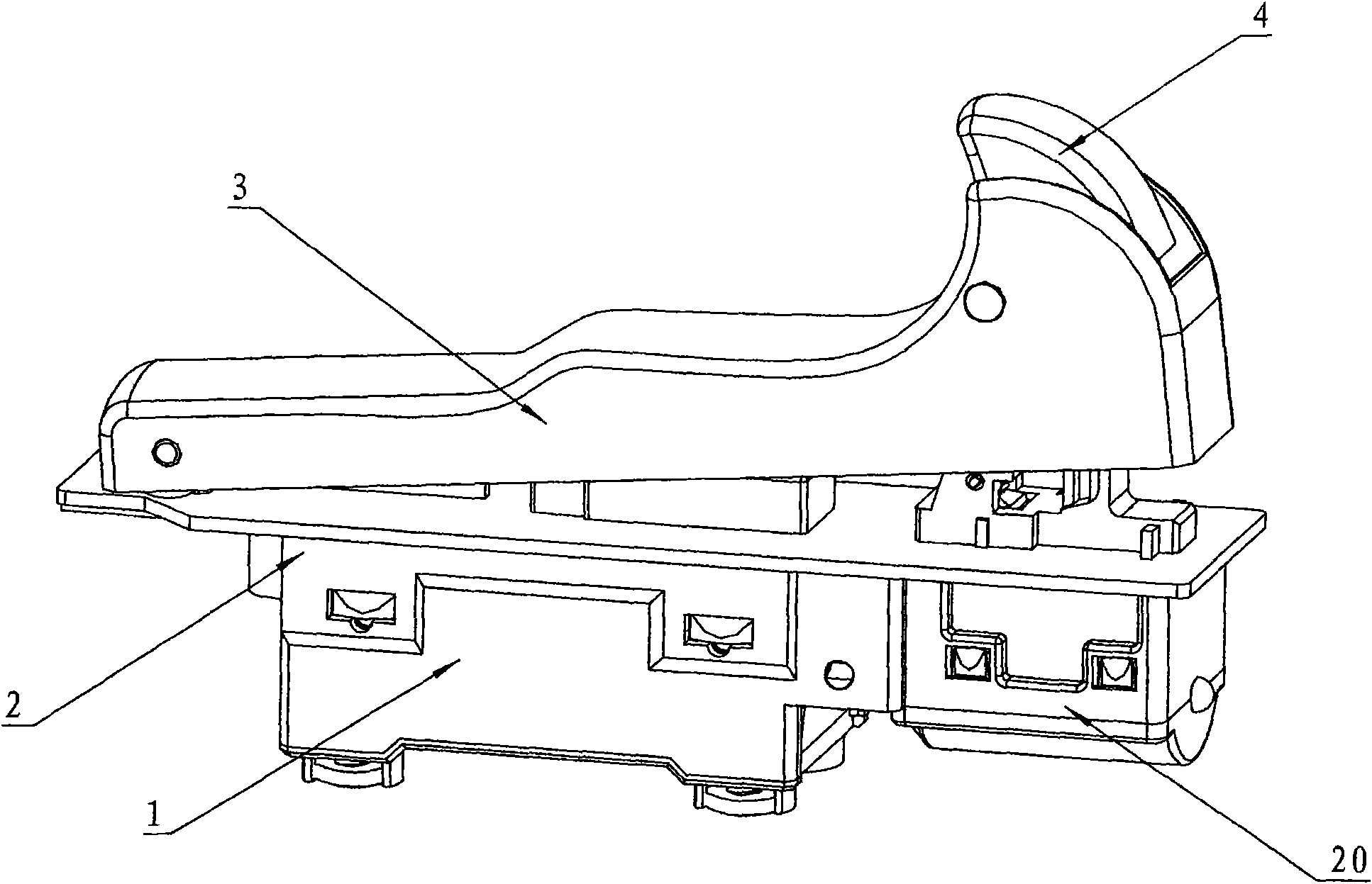
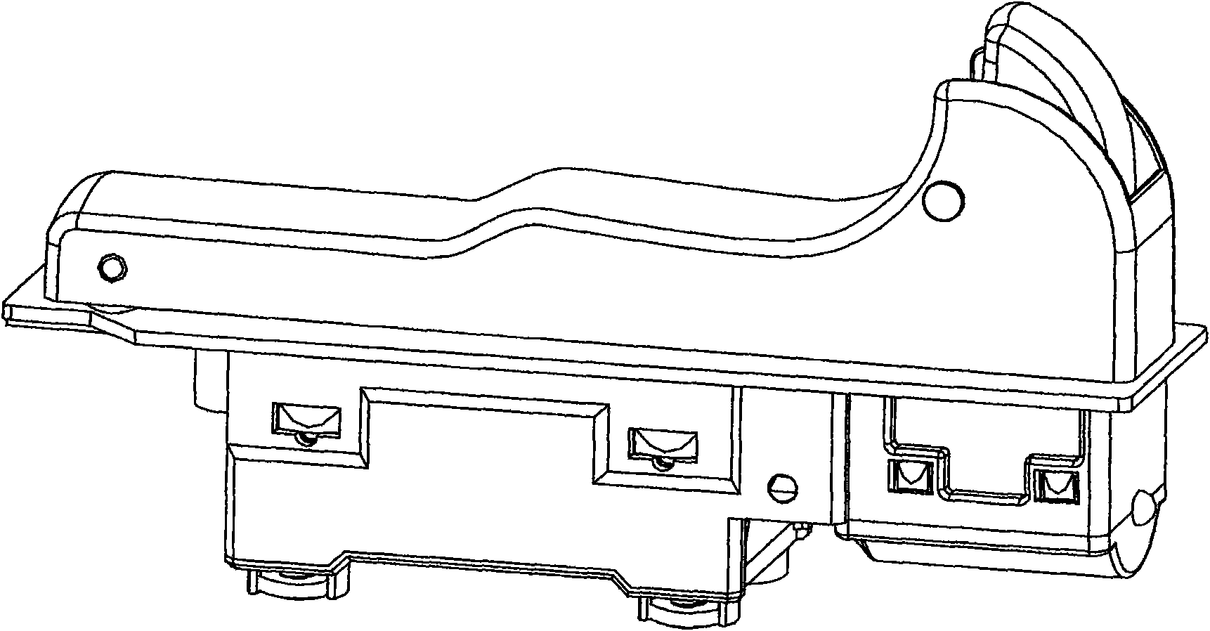
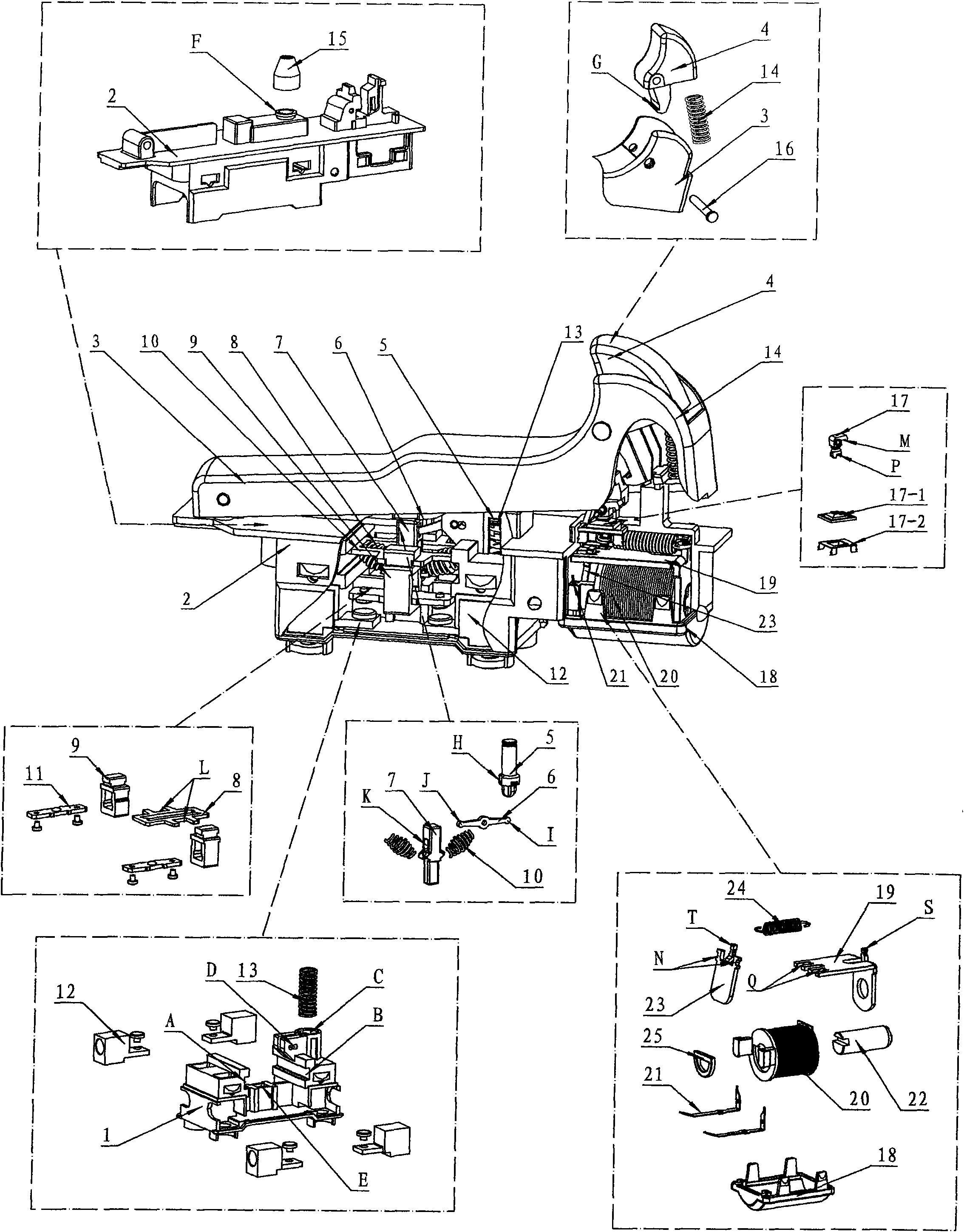
[0018] by Figure 1A , Figure 1B with figure 2 Shown, a trigger switch with power-off restart protection function is mainly composed of base body 1, housing 2, trigger 3, lock button 4, yoke 19, coil 20, iron core 22 and armature 23, among which: base The body 1, the housing 2, the trigger 3 and the lock button 4 and related structural elements constitute the mechanical structural part of the switch. The yoke 19, the coil 20, the iron core 22 and the armature 23 and related electromagnetic elements constitute the electromagnetic structural part of the switch. The trigger 3 makes the movable contact 11 and the terminal 12 produce closing and opening actions through the mechanical part and the electromagnetic structure part of the trigger switch.

[0019] The circular hole C of the base body 1 and the circular hole F of the housing 2 are sleeved with a push shaft 5 and a push shaft spring 13. The push shaft 5 can slide up and down to drive the pry bar 6 to be fixed on the base bod...


PUM


Abstract

The invention discloses a trigger switch with a power failure restart protection function, which mainly comprises a base body (1), a shell (2), a trigger (3), a lock knob (4), a magnetic yoke (19), a coil (20), a magnetic core (22) and an armature (23), wherein the base body (1), the shell (2), the trigger (3), the lock knob (4) and related structural elements form a mechanical structure part of the switch, and the magnetic yoke (19), the coil (20), the magnetic core (22), the armature (23) and relates electromagnetic elements form the electromagnetic structural part of the switch. The trigger switch formed by the mechanical structural part and the electromagnetic structural part can realize closed locking after the switch is switched on and the off functions of the switch when power failure occurs suddenly, and if the switch is expected to be switched on again, the trigger is required to be pressed again to realize the power failure restart protection function of the switch. The invention has compact structure and low manufacture cost, is suitable for large and middle sized angular finishing grinders, polishing machines, waxing machines and other electric tools, and accords with the national safety standard.

Description

Technical field [0001] The invention relates to a trigger switch, in particular, the switch has a power failure restart protection function, that is, the switch is suddenly cut off when the switch is normally energized and closed and locked, and the switch needs to be pressed again to realize the switch on again. Background technique [0002] The functions of this type of trigger switch currently on the market are basically similar, but have the following functional defects: [0003] 1. The conventional trigger switch only has the most basic on-off function, without the power-off restart protection function. In the energized state, that is, if the machine is in normal operation, if the power is suddenly cut off, if the user of the machine forgets to unlock the trigger switch, that is, the switch lock button is disconnected from the housing, the machine is still running when the power comes on, and the current of such switches is large. Used for high-power electric tools, it is ext...

Claims


Application Information

Patent Timeline
Patent Type & Authority Applications(China)
IPC IPC(8): H01H21/02H01H21/36H01H3/28
Inventor 倪圣珑
Owner ZHEJIANG JIABEN ELECTRONICS CO LTD
Why Eureka
Try Eureka