Gearbox improvement structure for electric vehicle

A technology of gearboxes and electric vehicles, which is applied to vehicle gearboxes, vehicle components, wheeled transmissions, etc., to facilitate human riding or carts and reduce transmission resistance

Inactive Publication Date: 2010-11-17
许晓华
View PDF6 Cites 4 Cited by
  • Summary
  • Abstract
  • Description
  • Claims
  • Application Information

AI Technical Summary

Problems solved by technology

However, this gear transmission mechanism needs to use a large force to overcome the resistance between the gears when the battery power is exhausted and the manpower is riding or pushing the cart.

Method used


Image

  • Gearbox improvement structure for electric vehicle
  • Gearbox improvement structure for electric vehicle
  • Gearbox improvement structure for electric vehicle

Examples


Embodiment Construction

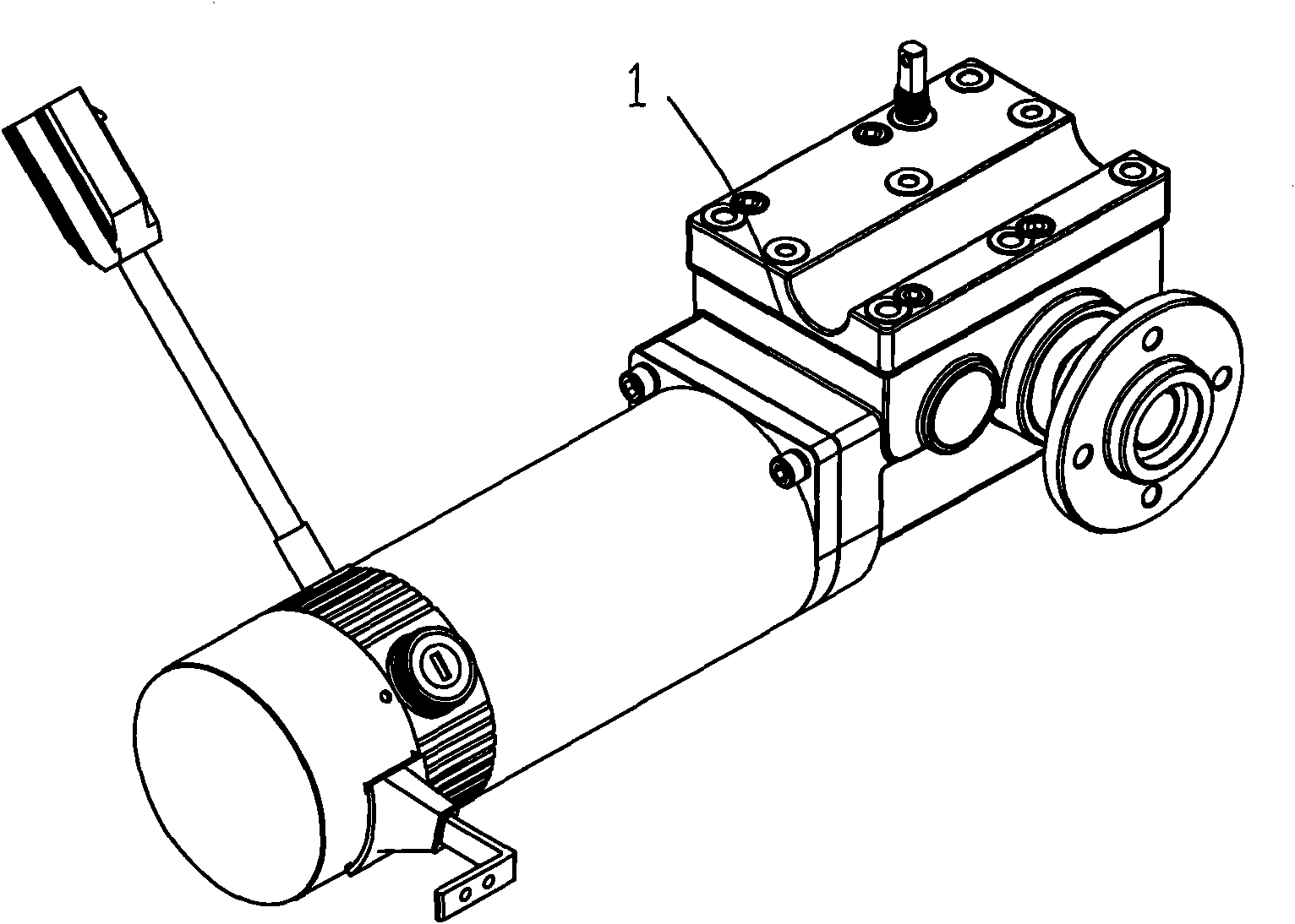
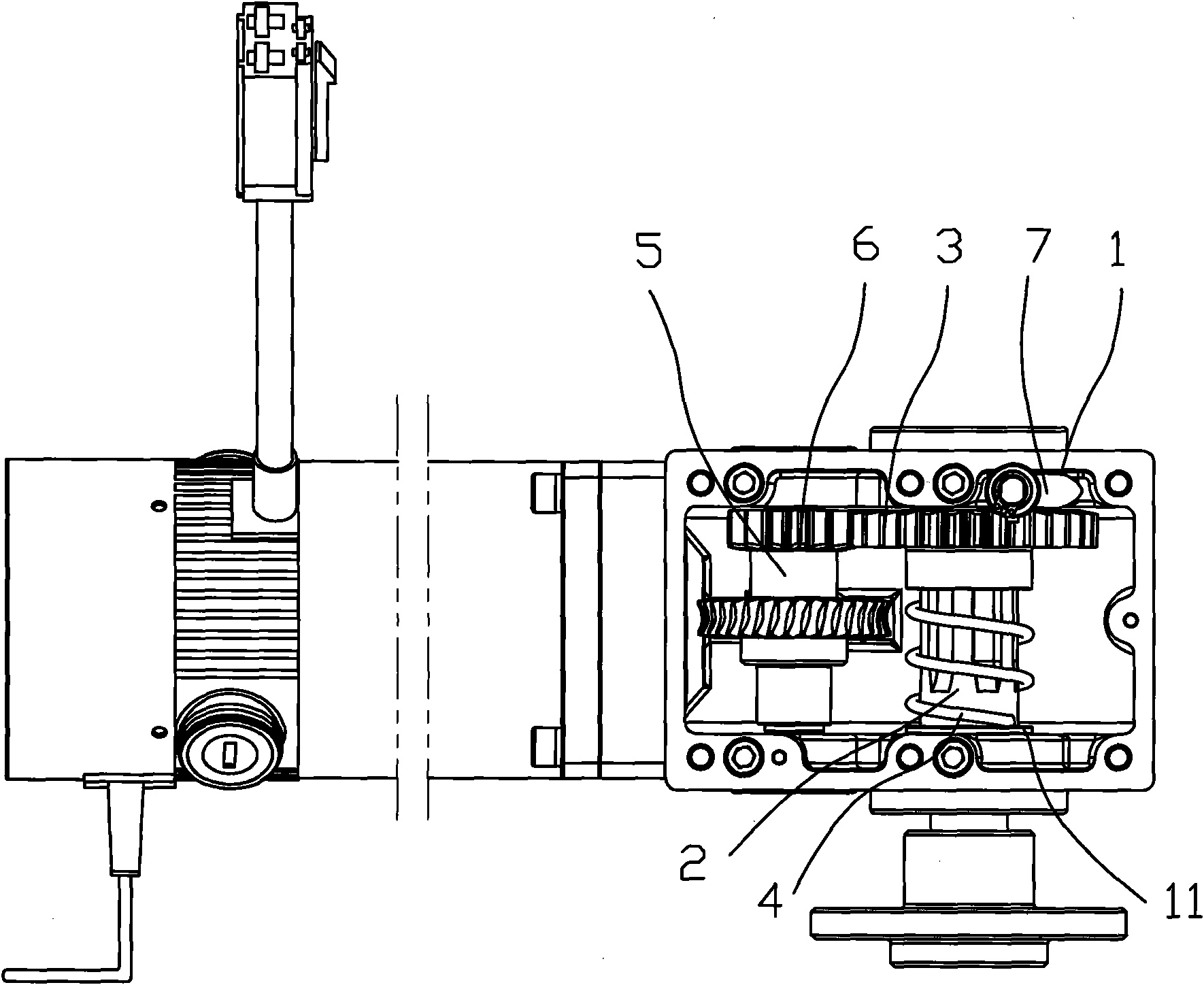
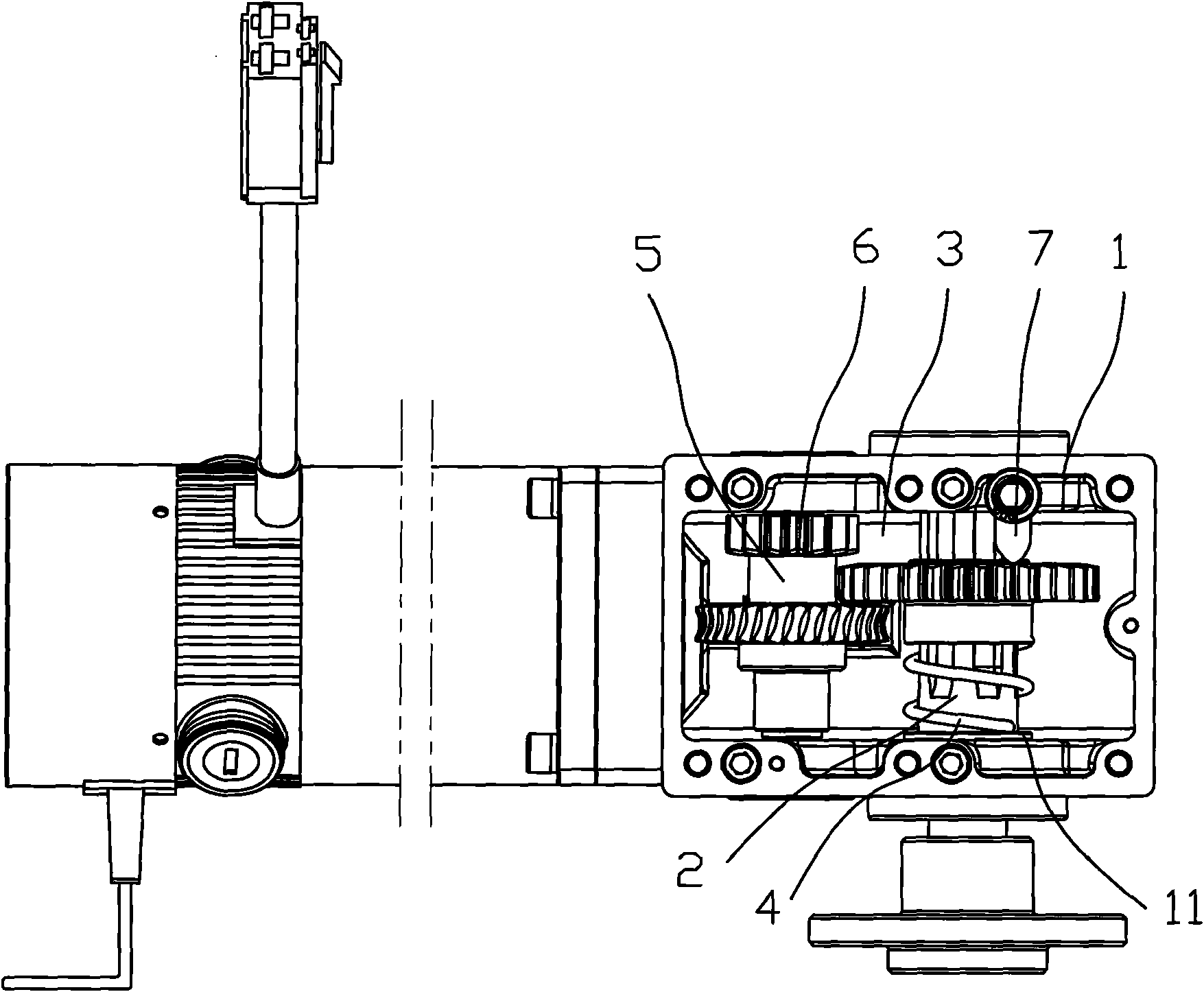
[0017] Such as Figure 1 to Figure 5 Shown here is an embodiment of an improved structure of an electric vehicle gearbox of the present invention, which includes a gearbox 1 and a transmission shaft 5 and an output shaft 2 mounted on the gearbox, and a driving gear 6 is provided on the transmission shaft. The output shaft is provided with a driven gear 3 that meshes with the driving gear 6, the driven gear 3 is slidably connected to the output shaft 2, and the gear box 1 is provided with a control driven gear to disengage from the driving gear and Engaged clutch device. The wheel shaft 2 and the driven gear 3 achieve a sliding connection through spline fitting. The clutch device includes a rotating head 7 arranged on the side wall of the gear box body. The rotating head 7 rotates and pushes the driven gear 3 to slide away from the driving gear 6 on the wheel shaft 2. The rotating head 7 is driven by the gear box. The outer handle 8 controls the rotation. The clutch device fu...


PUM


Abstract

The invention discloses a gearbox improvement structure for an electric vehicle, which comprises a gearbox, and a transmission shaft and an output shaft arranged on the gearbox. A driving gear is arranged on the transmission shaft; a driven gear which is engaged with the driving gear is arranged on the output shaft; the driven gear is connected on the output shaft in a sliding mode; and a clutch device which controls the driven gear and the driving gear to be disengaged and engaged is arranged on the gearbox. Because the clutch device which makes the driven gear to slide along a wheel axle so as to be disengaged from the driving gear is arranged on the gearbox, the electric vehicle gearbox improvement structure reduces the transmission resistance between gears during riding when the battery power is exhausted, and brings convenience to manual riding or pushing.

Description

Technical field [0001] The invention relates to an improved structure of an electric vehicle gear box. Background technique [0002] Electric bicycles use electric energy such as batteries and lithium batteries as auxiliary energy sources. They have two wheels and can realize human riding, electric or electric assist functions. Existing electric vehicles usually use gears as the transmission mechanism. For example, the Chinese utility model patent No. 200820037837.3 discloses a gear-driven electric vehicle, the battery is connected to the motor, the motor is installed on the frame, the wheel shaft is connected to the gear, and the transmission gear on the motor shaft matches the connected gear on the wheel shaft. . However, this gear transmission mechanism needs to use a relatively large force to overcome the resistance between the gears when the battery is exhausted for manual riding or carts. Summary of the invention [0003] The technical problem to be solved by the present ...

Claims


Application Information

Patent Timeline
Patent Type & Authority Applications(China)
IPC IPC(8): B62M11/00
Inventor 申屠君
Owner 许晓华
Why Eureka
Try Eureka