Scroll compressor

A scroll compressor and scroll technology, applied in the field of scroll compressors, can solve problems such as overcompression and loss increase, and achieve the effect of preventing overcompression and reducing overpressure loss

Active Publication Date: 2010-11-17
PANASONIC CORP
View PDF7 Cites 17 Cited by
  • Summary
  • Abstract
  • Description
  • Claims
  • Application Information

AI Technical Summary

Problems solved by technology

[0005] However, in the conventional structure described above, the point corresponding to the curling start angle of the wrap tooth outer wall of the orbiting scroll is in the rotation angle range of 15° to 40° after being separated from the wrap tooth inner wall of the fixed scroll. Inside, the discharge port communicates with the first compression chamber, so there is still the possibility of causing overcompression
Especially in the process of low compression ratio operation with the highest frequency in actual use, this overcompression obviously exists, leading to the problem of increased loss

Method used


Image

  • Scroll compressor
  • Scroll compressor
  • Scroll compressor

Examples


Embodiment 1

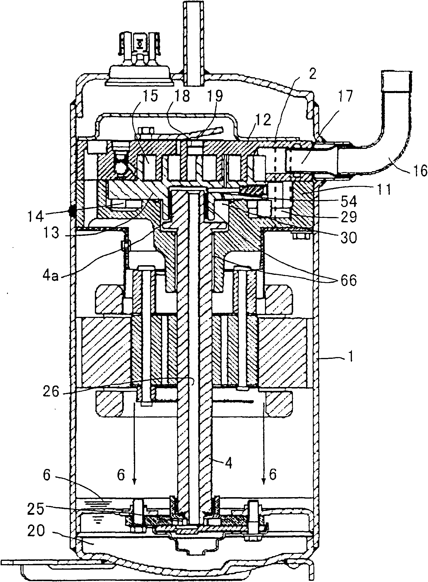
[0031] figure 1 It is a longitudinal sectional view of the scroll compressor in Embodiment 1 of the present invention. The operation and function of the scroll compression chamber will be described below.

[0032] Such as figure 1 As shown, the scroll compressor of the present invention is the main bearing part 11 of the crankshaft 4 fixed in the airtight container 1 by means of welding or heating, inserting, etc., and the fixed scroll fixed on the main bearing part 11 with screws 12, the orbiting scroll 13 engaged with the fixed scroll 12 is sandwiched to form a scroll compression mechanism 2. Between the orbiting scroll 13 and the main bearing member 11, there is provided a rotation restricting structure 14 formed of an Oldham ring or the like that prevents the orbiting scroll 13 from rotating and guides its movement along a circular orbit. By relying on the eccentric shaft portion 4a located at the upper end of the crankshaft 4 to drive the orbiting scroll 13 to rotate...

Embodiment 2

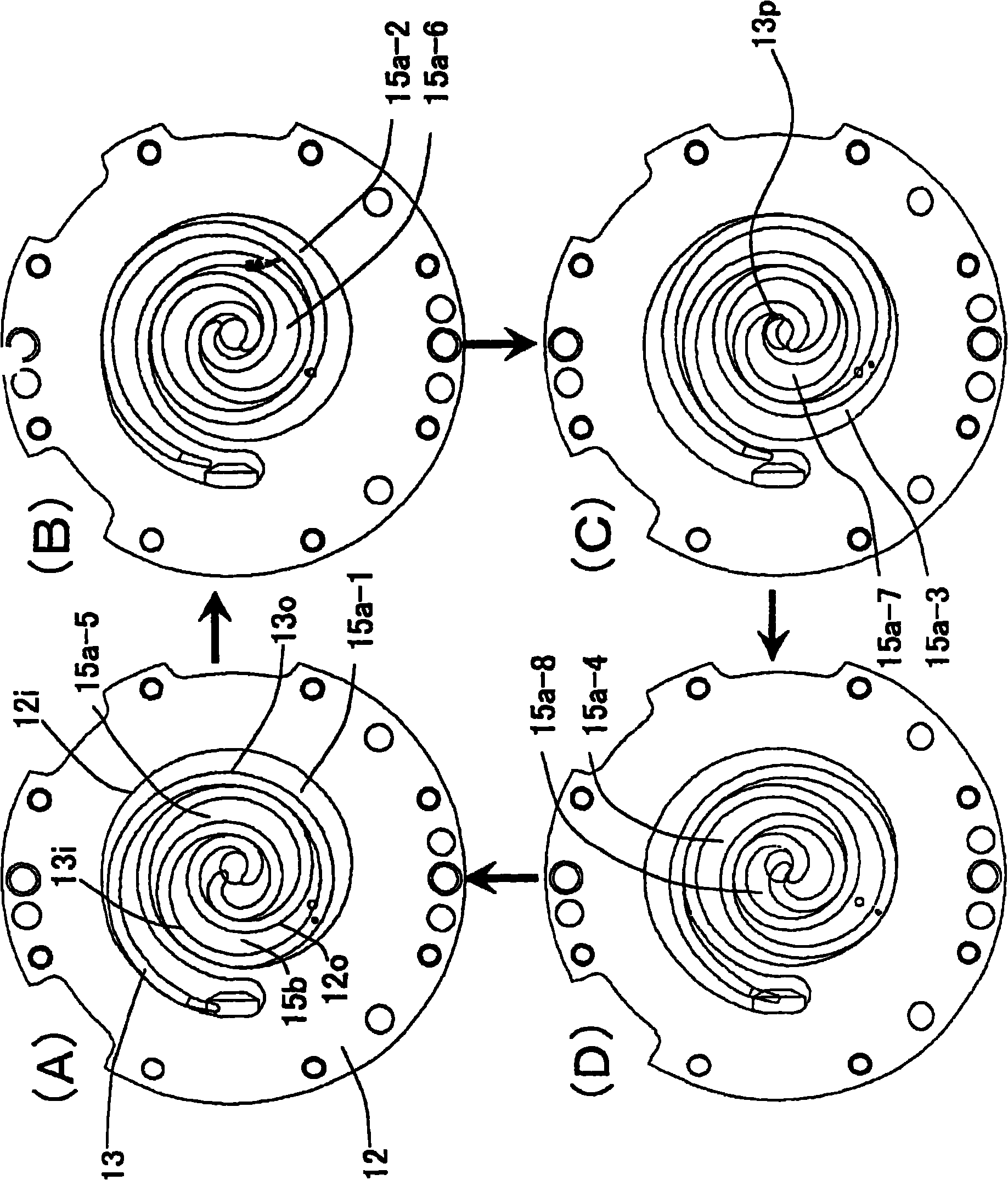
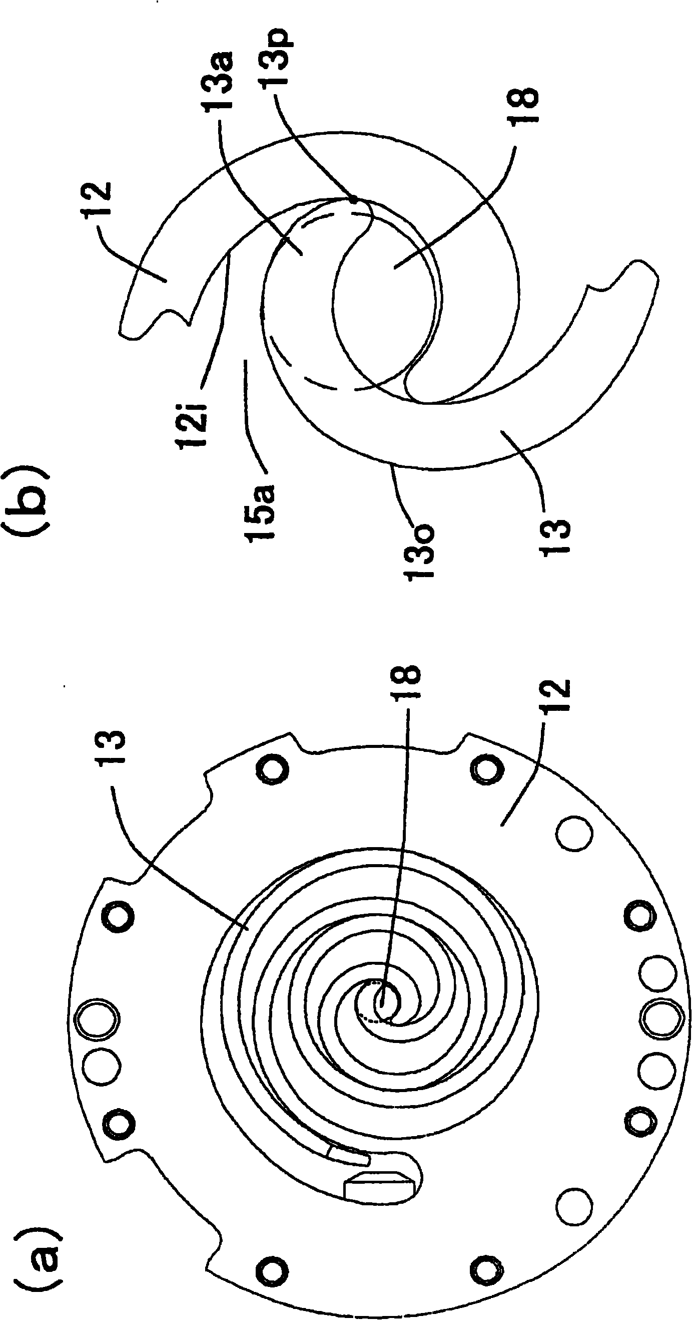
[0045] Figure 4 (a) is a cross-sectional view of the compression mechanism 2 of the scroll compressor according to Embodiment 2 of the present invention, showing that the point 13p corresponding to the wrap start angle of the wrap tooth outer wall 13o of the orbiting scroll 13 is about to start from the fixed scroll The state before the wrap inner wall 12i of the orbiting disk 12 separates and immediately before the concave portion 58 opens into the first compression chamber 15a. Figure 4 (b) is a partially enlarged view of the vicinity of the discharge port 18 . exist Figure 4 neutralize image 3 Only the same symbols are used for the same structure in , and the description is omitted here.

[0046] In the scroll compressor of this embodiment, as Figure 4 As shown in (b), a concave portion 58 communicating with the discharge port 18 is formed on the fixed scroll 12, and a point 13p corresponding to the wrap start angle of the wrap tooth outer wall 13o of the orbiting ...


PUM


Abstract

The present invention provides a scroll compressor, to solve the performance deteriorating problem generated by over pressure loss as the communicating path connected to the discharge outlet is narrower regardless whether or not the coolant gas in the compressing chamber achieves the prescribed pressure. Nearly simultaneously before or after the invention is separated by a first compression chamber (15a), the discharge outlet (18) passes across the vortex disc teeth (13a) of rotary scroll discs (13) to lead to the structure of the first compression chamber, as the discharge outlet (18) forms an opening directly in the first compression chamber (15a), and the communicating path can be thoroughly ensured added with the gap between the vortex disc teeth of the two rotary scroll discs, therefore the over-compression loss can be reduced.

Description

technical field [0001] The invention relates to a scroll compressor used in refrigerating devices such as heating and cooling air conditioners, refrigerators, or heat pump water heaters. Background technique [0002] Generally speaking, in the existing scroll compressors used for refrigeration, air-conditioning or refrigeration equipment, the fixed scroll and the orbiting scroll with spiral scroll teeth erected from the mirror plate are engaged with each other. A compression chamber is formed between them. When the orbiting scroll is rotated along a circular orbit by the rotation limiting structure on the basis of limiting the rotation, the compression chamber moves while changing the volume, and performs operations such as suction, compression, and exhalation. The refrigerant gas is gradually compressed with the rotation of the orbiting scroll, becomes high pressure as it moves toward the center, and is discharged into the inner space of the airtight container when it reac...

Claims


Application Information

Patent Timeline
Patent Type & Authority Applications(China)
IPC IPC(8): F04C18/02F04C29/00
CPCF04C18/0246
Inventor 作田淳河野博之大野龙一中井启晶森本敬桥本雄史阪井学
Owner PANASONIC CORP
Why Eureka
Try Eureka