Solenoid valve device and automatic paper feeder using same

An automatic paper feeding, solenoid valve technology, applied in valve device, valve operation/release device, valve lift and other directions, can solve the problems of collision sound, human unpleasant, etc. Collision sound effect

Inactive Publication Date: 2010-11-17
PRIMAX ELECTRONICS LTD
View PDF0 Cites 3 Cited by
  • Summary
  • Abstract
  • Description
  • Claims
  • Application Information

AI Technical Summary

Problems solved by technology

However, during operation, since the top 111 of the solenoid valve shaft 11 will collide with the bottom 1022 of the groove, a collision sound will be generated.
The collision sound will be amplified by the structure of the solenoid valve

Method used


Image

  • Solenoid valve device and automatic paper feeder using same
  • Solenoid valve device and automatic paper feeder using same
  • Solenoid valve device and automatic paper feeder using same

Examples


Example Embodiment

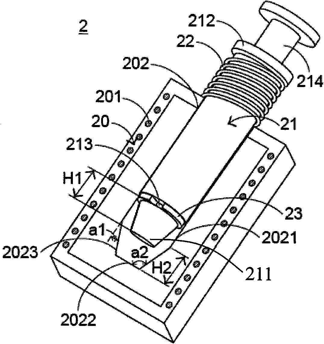
[0058] In order to reduce the collision sound, the solenoid valve device 2 of the present invention is specially provided with a noise reduction device, please refer to figure 2 , which is a schematic structural diagram of a preferred embodiment of the solenoid valve device of the present invention. The solenoid valve device 2 includes a solenoid valve body 20 , a solenoid valve shaft 21 , a spring 22 , an annular groove 213 and a muffler ring 23 . The solenoid valve body 20 has a solenoid coil 201 and a groove 202. The solenoid coil 201 surrounds the solenoid valve body 20 to generate magnetic force. The inner wall 2023 is located between the groove side wall 2021 and the groove bottom 2022, and the groove inner wall 2023 and the groove side wall 2021 have an included angle a1, and the groove inner wall 2023 and the groove bottom 2022 have another included angle a2.

[0059] The solenoid valve shaft 21 has a top 211 at one end of the solenoid valve shaft 21 and a flange 21...


PUM


Abstract

The invention relates to a solenoid valve device and an automatic paper feeder using the same. The solenoid valve device comprises a solenoid valve body, a solenoid valve shaft center, a spring, an annular groove and a muffling ring, wherein the annular groove surrounds the solenoid valve shaft center and is provided with the muffling ring. When the solenoid valve body is excited to adsorb the solenoid valve shaft center, the solenoid valve shaft center moves in the solenoid valve body and enables the muffling ring to collide with the solenoid valve body to reduce the colliding sound.

Description

technical field [0001] The invention relates to a power device, in particular to a solenoid valve device for converting electric energy into magnetic energy and an automatic paper feeder utilizing the solenoid valve device. Background technique [0002] The solenoid valve device is a device used to convert electrical energy into magnetic energy, and is widely used in various fields. In order to meet the needs of different devices, manufacturers of solenoid valve devices manufacture solenoid valve devices of various sizes according to various needs. [0003] For the structure of the solenoid valve unit, please refer to figure 1 , which is a structural schematic diagram of an existing solenoid valve device. The solenoid valve structure 1 includes a solenoid valve body 10, a solenoid valve axis 11 and a spring 12. The solenoid valve body 10 includes a solenoid coil 101 and a groove 102. The solenoid coil 101 surrounds the solenoid valve body 10, and the groove 102 includes a ...

Claims


Application Information

Patent Timeline
IPC IPC(8): F16K1/00F16K1/32F16K31/06B65H3/44B65H3/06B65H5/06
Inventor 王钟凯黄文安杨照民徐维熏
Owner PRIMAX ELECTRONICS LTD
Why Eureka
Try Eureka