
LED area light source device

A technology of LED surface light source and point light source, applied in the direction of plane light source, light source, electric light source, etc., can solve the problems of reduced brightness of outgoing light and light loss, etc.

Inactive Publication Date: 2010-11-17
YANCHENG SANDING ELECTRONICS TECH CO LTD
View PDF9 Cites 8 Cited by
  • Summary
  • Abstract
  • Description
  • Claims
  • Application Information

AI Technical Summary

Problems solved by technology

However, when the light is transmitted in the diffuser, part of the light will be absorbed by the diffuser and cause part of the light loss, thereby reducing the brightness of the outgoing light

Method used


Image

  • LED area light source device
  • LED area light source device
  • LED area light source device

Examples


Embodiment Construction

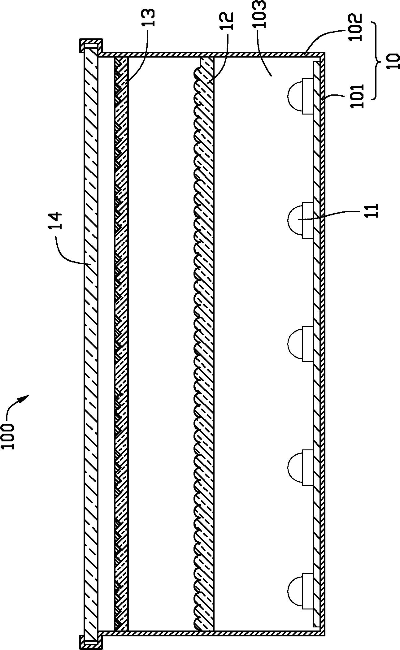
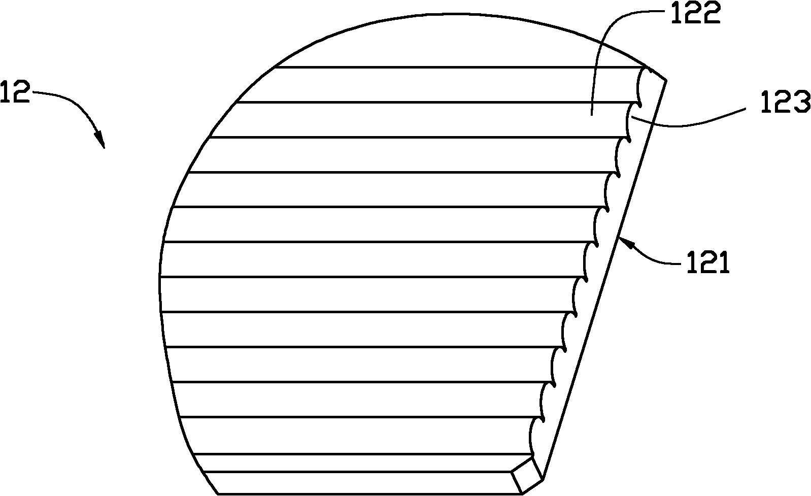
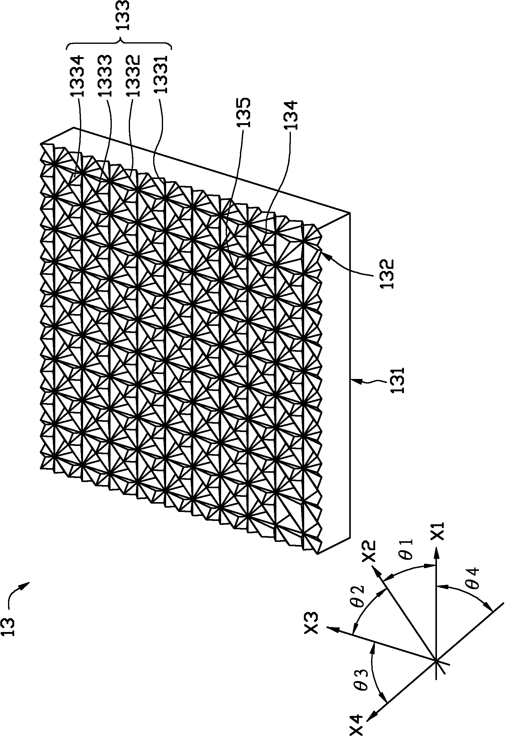
[0026] see figure 1 The LED surface light source device 100 includes a frame 10 , a plurality of point light sources 11 , a first prism sheet 12 , a second prism sheet 13 and a protection plate 14 . The frame 10 includes a bottom plate 101 and side walls 102 around the bottom plate 101 , the bottom plate 101 and the side walls 102 define a receiving chamber 103 . The frame 10 may be made of metal or plastic having high reflectivity, or metal or plastic coated with a high reflectivity coating. Multiple point light sources 11 are arranged on the bottom plate 101 . The first prism sheet 12 and the second prism sheet 13 have a size adapted to the housing cavity 103, and the first prism sheet 12 is positioned above the point light source 11, the second prism sheet 13 is positioned above the first prism sheet 12, and the frame 10 near the open end. Both the first prism sheet 12 and the second prism sheet 13 are substantially parallel to the base plate 101 . There is a first pred...


PUM


Abstract

The invention relates to an LED area light source device which comprises a framework, a plurality of point light sources, first transparent prismatic lenses and second transparent prismatic lenses, wherein the framework comprises a substrate, and the plurality of point light sources are arrayed on the substrate; the first prismatic lenses are arranged above the point light sources, the second prismatic lenses are arranged above the first prismatic lenses, and the first prismatic lenses and the second prismatic lenses are respectively provided with a light inlet surface and a light outlet surface opposite to the light inlet surface; a plurality of long strip-shaped arc protrusions are formed on the light outlet surfaces of the first prismatic lenses; a plurality of long strip V-shaped ridge structures extending along at least two different directions are formed on the light outlet surfaces of the second prismatic lenses and mutually staggered; a first preset distance is spaced between the first prismatic lenses and the point light sources; and a second preset distance is spaced between the second prismatic lenses and the first prismatic lenses.

Description

technical field [0001] The invention relates to a surface light source device, in particular to an LED surface light source device with double-layer prism sheets. Background technique [0002] LED is a point light source with a small luminous angle and strong directionality. In order to obtain a large enough luminous area, LED lighting devices usually arrange multiple LEDs in an array. However, when multiple point light sources illuminate an object at the same time, the illuminated object usually produces multiple shadows. In addition, the luminous intensity of the LED monomer is high, forming a strong direct glare (bright spot) on the light-emitting surface of the LED lamp, and it is a point light source distributed in a point shape when viewed from the outside. In order to avoid the ghosting of the light source, a surface light source device with good lighting function is obtained with a diffuser, so as to obtain uniform outgoing light. However, when the light is transmi...

Claims


Application Information

Patent Timeline
Patent Type & Authority Applications(China)
IPC IPC(8): F21S2/00F21V5/02F21V17/00F21V7/22F21Y105/00
CPCG02F1/133606F21Y2105/001F21V5/02F21V5/002G02F2001/133607F21Y2101/02F21V13/02F21Y2105/10F21Y2115/10G02F1/133607
Inventor 章绍汉
Owner YANCHENG SANDING ELECTRONICS TECH CO LTD
Learn More