
Flat plate type heat dissipation structure with high heat dissipation effect and manufacturing method thereof

A technology of heat dissipation structure and manufacturing method, which is applied to heat exchange equipment, indirect heat exchangers, metal extrusion dies, etc., to achieve the effect of increasing efficiency

Inactive Publication Date: 2010-11-17
CATCHER TECH
View PDF0 Cites 6 Cited by
  • Summary
  • Abstract
  • Description
  • Claims
  • Application Information

AI Technical Summary

Problems solved by technology

[0004] However, traditional heat pipes still have room for improvement in terms of their heat dissipation effects and usage methods (positioning of the evaporating section and condensing section) in actual use.

Method used


Image

  • Flat plate type heat dissipation structure with high heat dissipation effect and manufacturing method thereof
  • Flat plate type heat dissipation structure with high heat dissipation effect and manufacturing method thereof
  • Flat plate type heat dissipation structure with high heat dissipation effect and manufacturing method thereof

Examples


Embodiment Construction

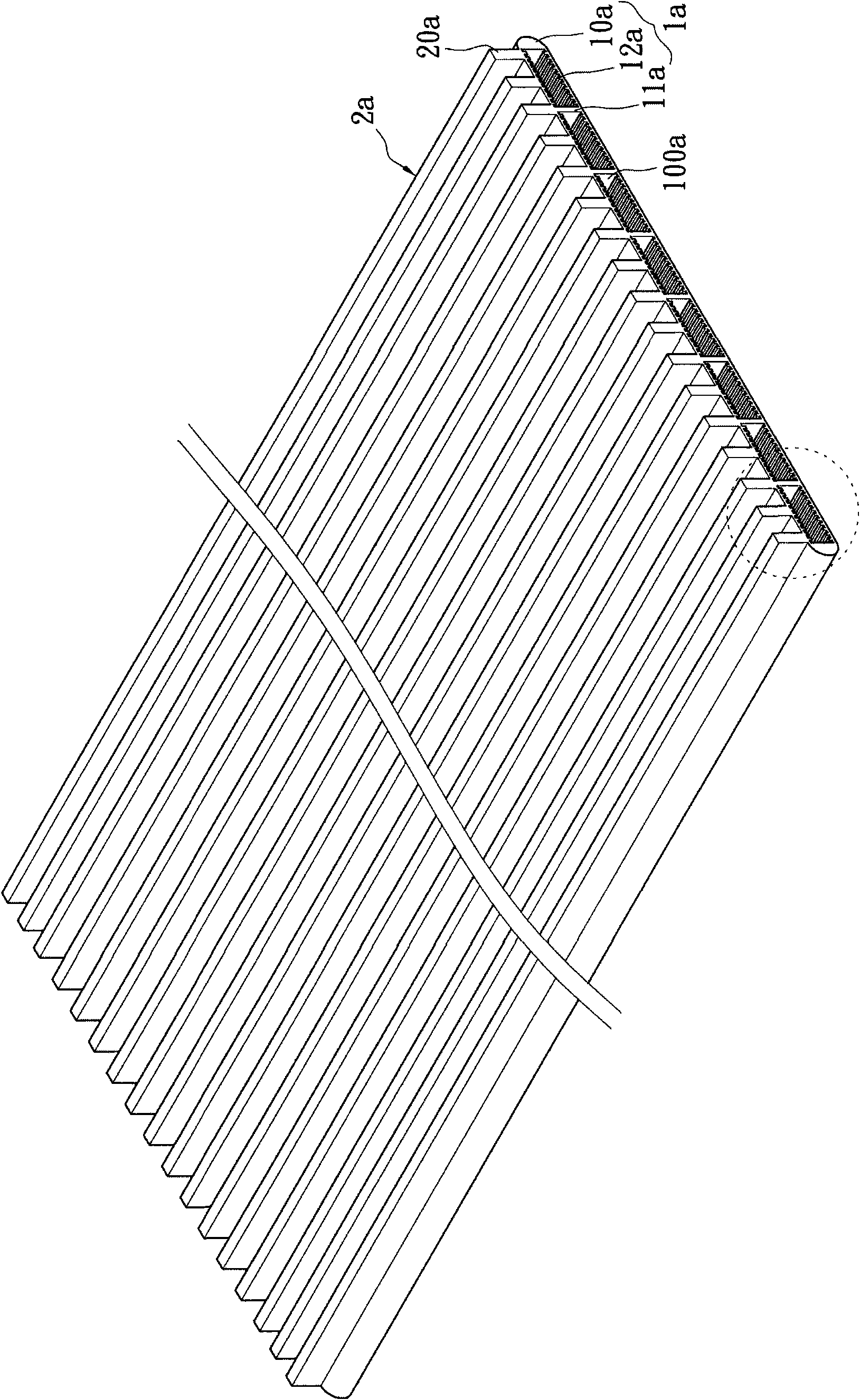
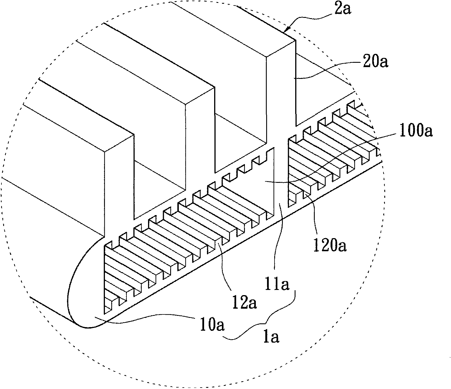
[0084] see Figure 1A to Figure 1B shown, where Figure 1A It is a three-dimensional schematic diagram of the first embodiment of the flat heat dissipation structure with high heat dissipation effect of the present invention; Figure 1B It is a partially enlarged view of the first embodiment of the flat plate heat dissipation structure with high heat dissipation effect of the present invention ( Figure 1A partial enlarged view). It can be seen from the above figures that the first embodiment of the present invention provides a flat heat dissipation structure with high heat dissipation effect, which includes: a first heat dissipation unit 1a and a second heat dissipation unit 2a.

[0085] Wherein, the first heat dissipation unit 1a has a vacuumized and closed hollow heat dissipation body 10a ( Figure 1A The front and rear ends of the hollow heat dissipation body 10a have been cut), a plurality of support plates 11a integrally formed in the hollow heat dissipation body 10a to ...


PUM


Abstract

The invention relates to a flat plate type heat dissipation structure with high heat dissipation effect, comprising a first heat dissipation unit and a second heat dissipation unit. The first heat dissipation unit is provided with a hollow heat dissipation body which is vacuumized and closed, a plurality of supporting plates which are formed into a whole in the hollow heat dissipation body to divide the interior of the hollow heat dissipation body into a plurality of containing spaces as well as a plurality of micro structures which are formed into a whole on the inner surface of the hollow heat dissipation body; wherein each containing space is filled with operating fluid. The second heat dissipation unit is formed into a whole on the outer surface of the first heat dissipation unit.

Description

technical field [0001] The invention relates to a flat heat dissipation structure and a manufacturing method thereof, in particular to a flat heat dissipation structure with high heat dissipation effect and a manufacturing method thereof. Background technique [0002] In today's various electronic devices, many electronic components that generate heat during operation are usually used. Especially in the case of increasingly high-speed calculations, these electronic components will inevitably generate more heat than previous electronic components. Taking the central processing unit as an example, with the improvement of the processing speed and performance of the central processing unit, the heat output of the current central processing unit has increased, and the higher operating frequency has also increased the wattage during work. The high temperature will reduce the life of the central processing unit, especially when the excessive heat cannot be effectively removed, it i...

Claims


Application Information

Patent Timeline
Patent Type & Authority Applications(China)
IPC IPC(8): F28F3/04F28F3/12F28F21/08F28F3/08B21C25/02F28D15/02
Inventor 洪水树李坚玮李士玮
Owner CATCHER TECH
Learn More