Hall chip magnetic flux test device

A Hall chip and testing device technology, applied in the direction of the size/direction of the magnetic field, can solve the problems of test deviation, residual magnetism, misjudgment, etc.

Active Publication Date: 2010-11-17
ZHEJIANG HENGTUO ELECTRONIC TECH CO LTD
View PDF5 Cites 9 Cited by
  • Summary
  • Abstract
  • Description
  • Claims
  • Application Information

AI Technical Summary

Problems solved by technology

In the SOT23 package test, because the traditional SOT23 package test sorter does not install a magnetic field, it is impossible to test the magnetic flux of the Hall chip
And the test head and suction nozzle part of the traditional SOT23 packaging test sorting machine are made of magnetic materials, so even if a

Method used


Image

  • Hall chip magnetic flux test device
  • Hall chip magnetic flux test device
  • Hall chip magnetic flux test device

Examples


Embodiment Construction

[0022] The technical solutions of the present invention will be further described in detail below in conjunction with the accompanying drawings and embodiments.

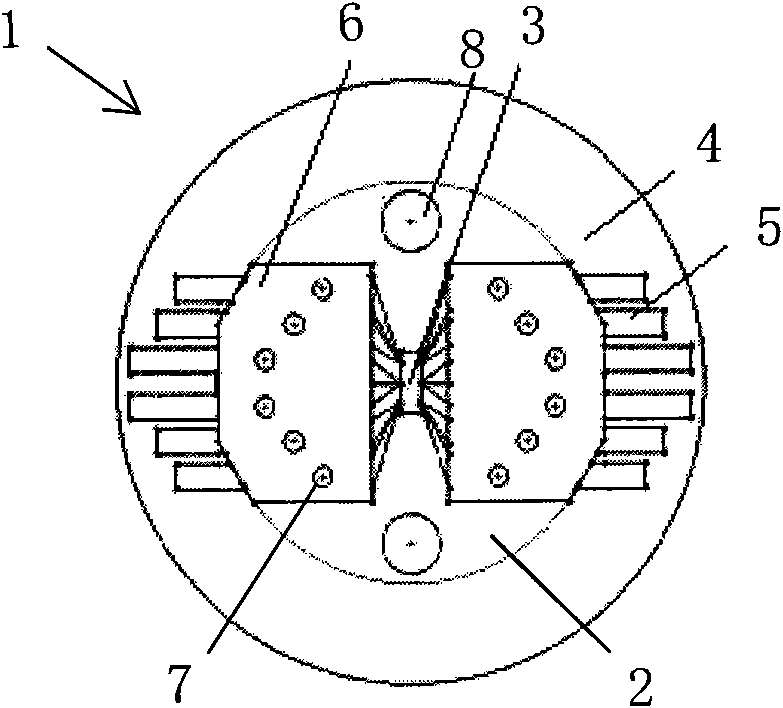
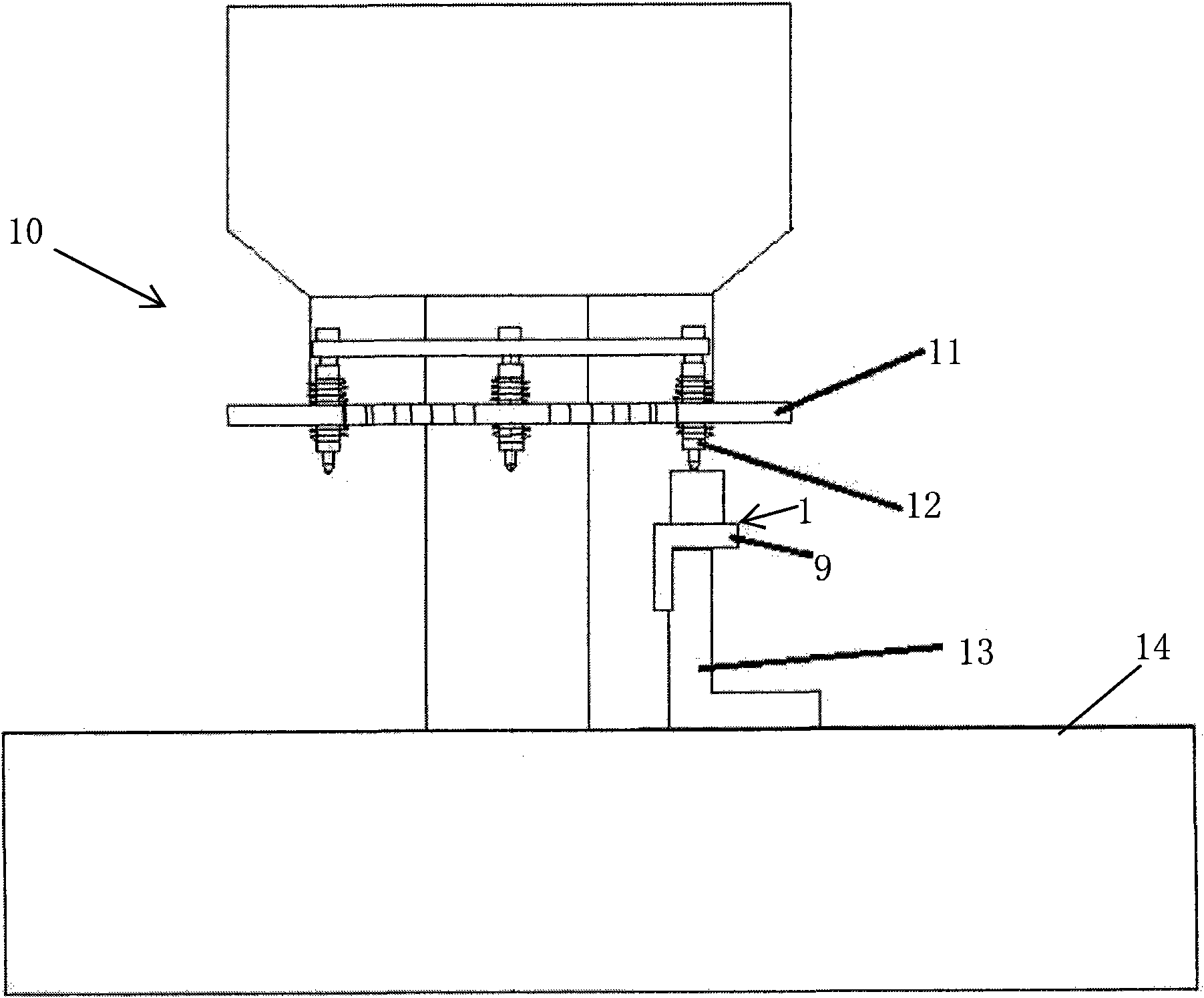
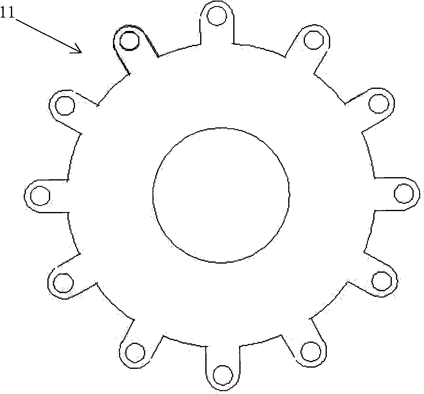
[0023] like figure 1 As shown, a Hall chip magnetic flux testing device 1 for a SOT23 package testing and sorting machine according to the present invention is shown. This test device 1 comprises a test stand 9 (such as figure 2 As shown), a coil 4 is wound on the test support, and a test seat 2 is installed on the upper end of the test support, and the test seat 2 is fixed on the test support by screws 8. A test fixture 3 for placing the Hall chip to be tested is arranged in the test socket 2 . The test device 1 also includes two rows of gold fingers 5 that are electrically connected to the test fixture 3 so as to be in electrical contact with each pin of the chip under test placed in the test fixture 3, and the gold fingers are the pins of the chip under test. All signals are transmitted through golden fingers...


PUM


Abstract

The invention relates to a Hall chip magnetic flux test device (1) for use in a SOT23 encapsulation test sorter, which is characterized in that the device (1) comprises a test support (9), a test seat (2) fixed on the upper end of the test support (9), a test clamp (3) which is arranged in the test seat (2) for holding a tested Hall chip, a plurality of gold fingers (5) electrically connected with the test clamp (3), a cover plate (6) positioned above the gold fingers (5) and a coil (4) wound on the test support (9), wherein the gold fingers (5) are fixed between the cover plate (6) and the test seat (2). The device can test the magnetic flux of the Hall chip in a SOT23 encapsulation test.

Description

technical field [0001] The invention relates to a Hall chip magnetic flux testing device, which is used for testing the magnetic flux of mass-produced Hall chips during SOT23 package testing. Background technique [0002] The Hall effect is a kind of magnetoelectric effect. When the current passes through the conductor in the magnetic field in the direction perpendicular to the external magnetic field, a potential difference will appear between the two end faces of the conductor perpendicular to the direction of the magnetic field and the current. The phenomenon is called the Hall effect. The Hall sensor is a sensor that uses the Hall element to convert the measured physical quantity (such as current, magnetic field, displacement, pressure, etc.) into an electromotive force output based on the Hall effect principle. It has the advantages of simple structure, small size, no contact, high reliability and easy miniaturization, so it has been widely used in measurement technolo...

Claims


Application Information

Patent Timeline
IPC IPC(8): G01R33/02
Inventor 罗立权杨连宏
Owner ZHEJIANG HENGTUO ELECTRONIC TECH CO LTD
Why Eureka
Try Eureka