Mask knife edge moving device of photo-etching machine

A technology for mobile devices and lithography machines, which is applied in the field of lithography machines, can solve problems such as lack of equipment, and achieve the effect of improving flexibility and improving uniformity of illumination

Inactive Publication Date: 2010-11-17
INST OF OPTICS & ELECTRONICS - CHINESE ACAD OF SCI
View PDF5 Cites 10 Cited by
  • Summary
  • Abstract
  • Description
  • Claims
  • Application Information

AI Technical Summary

Problems solved by technology

[0002] In the lithography machine, it is often necessary to uniformly illuminate different positions or different shape areas on the mask, which can improve the uniformity of illumination and the flexibility of production and processing, and more im

Method used


Image

  • Mask knife edge moving device of photo-etching machine
  • Mask knife edge moving device of photo-etching machine
  • Mask knife edge moving device of photo-etching machine

Examples


Example Embodiment

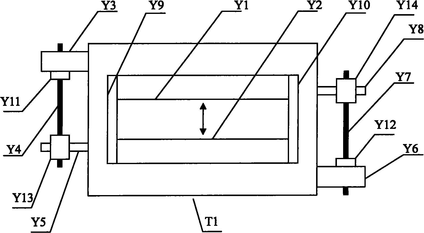
[0009] Such as figure 1 As shown, in the embodiment of the present invention, the Y-direction mask knife edge moving device is composed of upper and lower blade clamp parts. The Y-up blade clamp part is composed of blade clamp Y1, precision ball screw Y7, screw nut Y14, driving rod Y8, motor Y6, coupling Y12, and grating Y10.

[0010] The Y-down blade clamp part is composed of blade clamp Y2, precision ball screw Y4, screw nut Y13, driving rod Y5, motor Y3, coupling Y11, and grating Y9.

[0011] The Y-up blade clamp Y1 is installed on the driving rod Y8, the motor Y6 is connected to one end of the precision ball screw Y7 through the coupling Y12, the other end of the precision ball screw Y7 is connected to the screw nut Y14, and the screw nut Y14 is connected to Drive rod Y8 to connect. The detection grating Y10 is installed on the right side of the blade holder Y1 and perpendicular to the blade holder Y1. When the blade holder Y1 needs to move up and down, the computer sends a ...


PUM


Abstract

The invention discloses a mask knife edge moving device of a photo-etching machine. The device adopts a structure with a double-layer unit and two groups of independent assemblies, and consists of an X-direction slit knife edge moving device and a Y-direction slit knife edge moving device with the same structures; the X-direction slit knife edge moving device realizes X-direction left and right independent translation, and the Y-direction slit knife edge moving device realizes Y-direction up-and-down independent translation; the X-direction slit knife edge moving device and the Y-direction slit knife edge moving device are assembled and superposed to realize the X-direction left and right translation and the Y-direction up-and-down translation respectively; and the X-direction slit knife edge moving device or the Y-direction slit knife edge moving device consists of two blade clips, two precision ball screws, two screw nuts, two drive rods, two motors, two couplings, two gratings, a computer and a mask table. The device can realize an illumination area of a mask at different positions and with automatic control and adjustment of shape and size.

Description

technical field [0001] The invention relates to a mask knife edge moving device of a lithography machine, which belongs to the technical field of lithography machines. technical background [0002] In the lithography machine, it is often necessary to uniformly illuminate different positions or different shape areas on the mask, which can improve the uniformity of illumination and the flexibility of production and processing, and more importantly, greatly improve the quality of lithography. However, the original The current lithography machine does not have the illumination area selection function that can automatically control and adjust the different positions of the mask and the size and shape. Contents of the invention [0003] The technical problem of the present invention is: to overcome the deficiencies of the prior art, to provide a mask knife-edge moving device for photolithography machine, to realize the uniform illumination area selection in which the mask is in ...

Claims


Application Information

Patent Timeline
IPC IPC(8): G03F7/20
Inventor 邢薇胡松赵立新罗正全马平徐文祥
Owner INST OF OPTICS & ELECTRONICS - CHINESE ACAD OF SCI
Why Eureka
Try Eureka