Shift register circuit and shift register

A technology of shift register and circuit, which is applied in the field of shift register and shift register circuit, can solve the problem of low conduction current, and achieve the effect of solving low temperature start-up

Active Publication Date: 2010-11-17
AU OPTRONICS CORP
View PDF4 Cites 17 Cited by
  • Summary
  • Abstract
  • Description
  • Claims
  • Application Information

AI Technical Summary

Problems solved by technology

[0004] The purpose of the present invention is to provide a shift register circuit, even if the conduction current of the transistor is low in a low temperature environment, it can still generate a driving pulse signal normally, so as to solve the problem of starting at low temperature

Method used


Image

  • Shift register circuit and shift register
  • Shift register circuit and shift register
  • Shift register circuit and shift register

Examples


Embodiment Construction

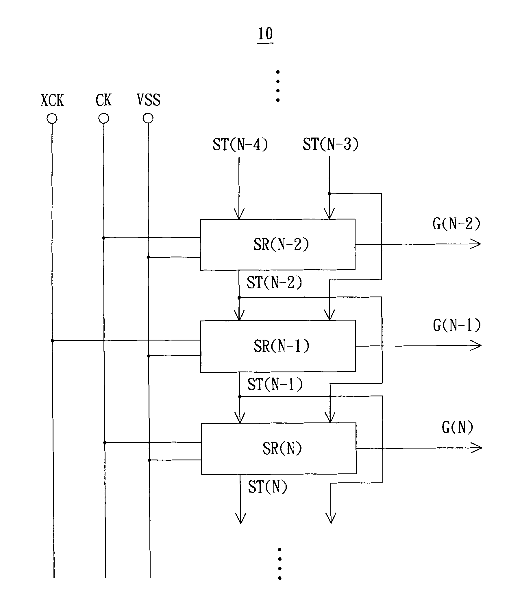
[0033] see figure 1 , which shows a schematic diagram of a partial structure of a shift register circuit proposed in relation to the first embodiment of the present invention. Such as figure 1 As shown, the shift register circuit 10 is applicable to a gate driving circuit of a display, but the present invention is not limited thereto, for example, it can also be applied to a source driving circuit of a display. Specifically, the shift register circuit 10 includes a plurality of shift registers such as SR(N-2), SR(N-1) and SR(N), which utilize multi-phase clock pulses such as two-phase clock pulses XCK, CK to generate gate drive pulse signal, but the present invention is not limited thereto; in this embodiment, shift registers SR(N-2), SR(N-1) and SR(N) are used to sequentially generate gate drive The pulse signals G(N-2), G(N-1) and G(N), N is a positive integer.

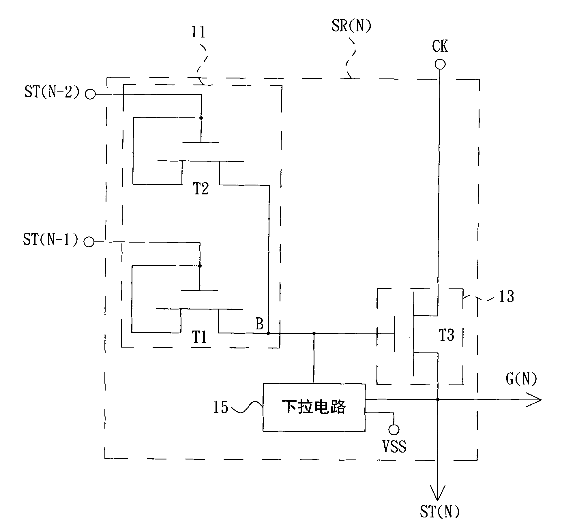
[0034]More specifically, the shift register SR(N-2) is electrically coupled to the power supply potential VSS ...


PUM


Abstract

The invention relates to a shift register circuit. The shift register circuit comprises a plurality of shift registers for outputting a plurality of drive pulse signals in turn, wherein in M shift registers for outputting M drive pulse signals in turn, the last shift register for outputting the drive pulse signals receives the enabling of (M-1) start pulse signals output by (M-1) shift registers for first outputting the drive pulse signals in turn to generate drive pulse signals, and M is a positive integer and more than 2. In addition, the invention also provides the shift register.

Description

technical field [0001] The invention relates to the field of display technology, and in particular to a shift register circuit and a shift register. Background technique [0002] Using amorphous silicon (a-Si) technology to make shift registers in the gate drive circuit of liquid crystal displays is the mainstream of thin film transistor liquid crystal display technology at present, which has the advantages of saving integrated circuit (IC) costs, simplifying the manufacturing process of modules and Advantages such as increasing the utilization efficiency of the glass substrate. Here, the shift register circuit includes a plurality of cascade-coupled shift registers to sequentially generate a plurality of driving pulse signals; start pulse signal. [0003] However, in some harsh environments, such as when the panel is operated at low temperature, the conduction current of the thin film transistor will drop sharply due to the temperature, so that the shift register circuit ...

Claims


Application Information

Patent Timeline
Patent Type & Authority Applications(China)
IPC IPC(8): G11C19/28G09G3/36
Inventor 邱振伦廖一遂陈柄霖陈冠宇
Owner AU OPTRONICS CORP
Why Eureka
Try Eureka