Multi-bus bar
A technology of surface wave filter and surface acoustic wave, which is applied in the direction of electrical components and impedance networks, can solve the problems of reducing device yield and deteriorating device performance
- Summary
- Abstract
- Description
- Claims
- Application Information
AI Technical Summary
Problems solved by technology
Method used
Image
Examples
Embodiment 1
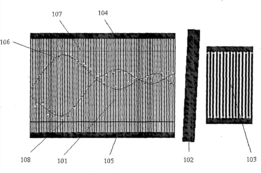
[0020] Such as figure 1 As shown, the multi-bus single-channel surface acoustic wave filter includes an input IDT 101 integrated on a piezoelectric substrate, a shielding strip 102 and an output IDT 103 . The IDT 101 at the input end is an accidially weighted IDT, and the IDT 103 at the output end is an isodigital IDT. A thick and thin multi-bus structure is adopted on the input IDT 101, including the thick bus bars 104, 105 connecting the fingers, and the weighted envelope 106 between the thick bus bar 104 and the cut finger. A thin bus bar 107 , and a thin bus bar 108 between the thick bus bar 105 and the incisor weighted envelope 106 . The width of the interdigitated fingers of the weighted transducer 101 at the input end is 14um, and the width of the thin busbars 107, 108 is 11um. The sound-absorbing material is applied to the area between the thick bus bar 104 and the thin bus bar 107 , and the area between the thick bus bar 105 and the thin bus bar 108 .
Embodiment 2
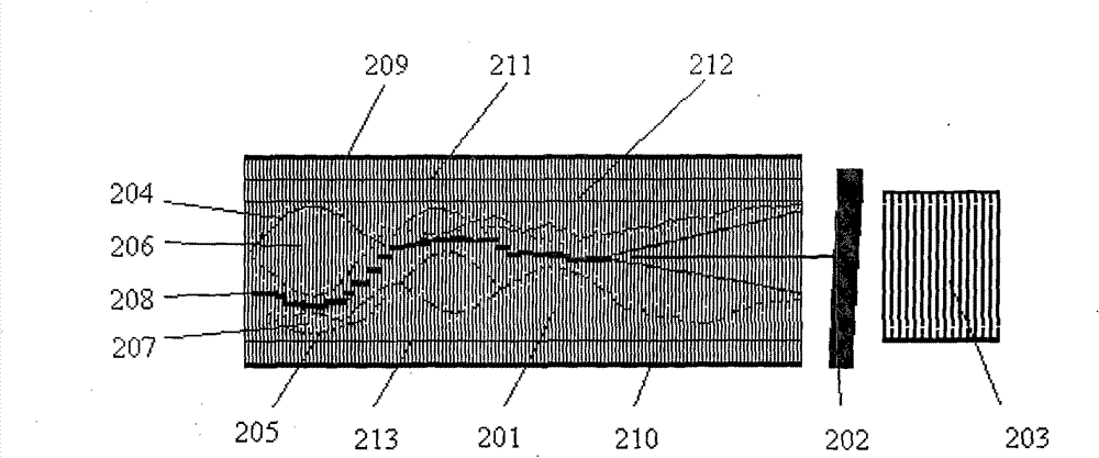
[0022] Such as figure 2 As shown, the dual-channel surface acoustic wave filter with multiple bus bars sharing comb electrodes includes an input IDT 201 , a shielding bar 202 and an output IDT 203 integrated on a piezoelectric substrate. The IDT 201 at the input end is two juxtaposed IDTs with weighted abscisal fingers. The main lobe areas of the weighted envelopes 204 and 205 of the abscisal fingers are arranged in a staggered manner, including two transmission channels 206 and 207, sharing one Comb electrodes 208 . The IDTs 201 at the input end share an IDT 203 at the output end. The input interdigital transducer 201 adopts a multi-bus structure with one thick and one thin and one thick and multiple thin, including thick bus bars 209 and 210 connecting each interdigital finger, and between the thick bus bar 209 and the weighted envelope 204 The thin bus bars 211 , 212 between them, and the thin bus bar 213 between the thick bus bar 210 and the cut-finger weighted envelope...
Embodiment 3
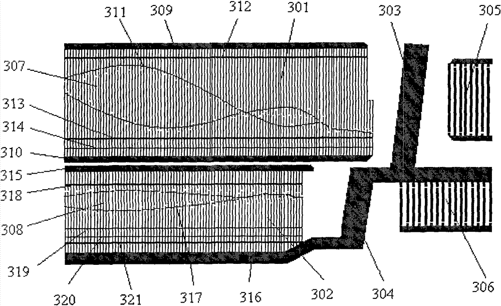
[0024] Such as image 3 As shown, the independent dual-channel surface acoustic wave filter with multiple bus bars includes input IDTs 301, 302 integrated on the piezoelectric substrate, shielding strips 303, 304 and output IDTs 305, 306, the transmission channels 307 and 308 are independent of each other. The IDTs 301 and 302 at the input end are accidially weighted IDTs, and the IDTs 305 and 306 at the output end are isodigital transducers. On the input interdigital transducer 301, a multi-bus structure with one thick and one thin and one thick and multiple thin is adopted, including the thick bus bars 309 and 310 connecting each interdigital finger, and the weighted envelope between the thick bus bar 309 and the cut finger Thin bus bars 312 between lines 311 , and thin bus bars 313 , 314 between thick bus bars 310 and cut finger weighting envelope 311 . The width of the interdigital fingers of the input IDT 301 is 10 um, the width of the thin bus bars 312 and 313 is 15 um...
PUM
 Abstract
Description
Claims
Application Information
 - R&D Engineer
- R&D Manager
- IP Professional
- Industry Leading Data Capabilities
- Powerful AI technology
- Patent DNA Extraction
Browse by: Latest US Patents, China's latest patents, Technical Efficacy Thesaurus, Application Domain, Technology Topic, Popular Technical Reports.
© 2024 PatSnap. All rights reserved.Legal|Privacy policy|Modern Slavery Act Transparency Statement|Sitemap|About US| Contact US: help@patsnap.com


