
Decoding method of MIMO space multiplexing and device thereof

A technology of spatial multiplexing and decoding device, applied in the field of MIMO, can solve the problem of high computational complexity and achieve the effect of low computational complexity

Inactive Publication Date: 2010-11-17
COMBA TELECOM SYST CHINA LTD
View PDF0 Cites 4 Cited by
  • Summary
  • Abstract
  • Description
  • Claims
  • Application Information

AI Technical Summary

Problems solved by technology

[0007] In the calculation of the pseudo-inverse of the weighted matrix W, one of the methods of the QR decomposition algorithm and the Cholesky decomposition algorithm can be used for calculation, but the computational complexity is relatively high; in addition, the matrix pseudo-inverse calculation of the weighted matrix W can also be directly performed , but the computational complexity is higher

Method used


Image

  • Decoding method of MIMO space multiplexing and device thereof
  • Decoding method of MIMO space multiplexing and device thereof
  • Decoding method of MIMO space multiplexing and device thereof

Examples


Embodiment 1

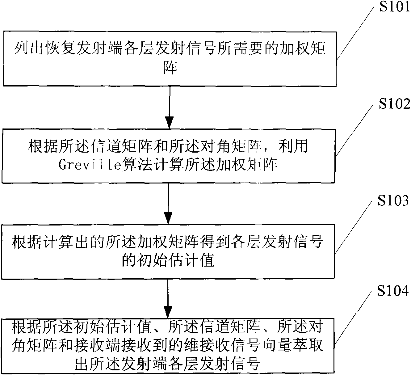
[0029] The decoding method of MIMO spatial multiplexing of the present invention, such as figure 1 , including the steps:

[0030] S101. Obtain the M required to recover the transmitted signals of each layer at the transmitting end T × M R dimension weighting matrix W; where W=(H H H+D 2 ) -1 h H , D is a diagonal matrix whose diagonal element values ​​are the reciprocals of the signal-to-noise ratios of each transmitting antenna at the transmitting end, H represents the channel matrix, and M T Indicates the number of transmit antennas, M R Indicates the number of receiving antennas at the receiving end.

[0031] S102. According to the channel matrix H and the diagonal matrix D, use a Greville algorithm to calculate the weight matrix W.

[0032] In a preferred embodiment, according to the channel matrix H and the diagonal matrix D, the weighting matrix W is calculated using the Greville algorithm, specifically:

[0033] According to the formula Calculate the first r...

Embodiment 2

[0072] Compared with the MIMO spatial multiplexing decoding method in Embodiment 1, the MIMO spatial multiplexing decoding device of the present invention, such as Figure 4 ,include:

[0073] Calculation module, used to obtain the M required to restore the transmission signal of each layer at the transmitting end T × M R dimension weighting matrix W; where W=(H H H+D 2 ) -1 h H , D is a diagonal matrix whose diagonal element values ​​are the reciprocals of the signal-to-noise ratios of each transmitting antenna at the transmitting end, H represents the channel matrix, and M T Indicates the number of transmit antennas, M R Indicates the number of receiving antennas at the receiving end; and according to the channel matrix H and the diagonal matrix D, the weighting matrix W is calculated using the Greville algorithm.

[0074] A judging module, configured to obtain an initial estimated value of the transmitted signal of each layer according to the calculated weighting mat...


PUM


Abstract

The invention discloses a decoding method of MIMO space multiplexing and a device thereof. The decoding method comprises the following steps: acquiring the MT*MR dimensional weighting matrix W required for regaining each layer of transmitting signals of a transmitting end, wherein W=(HHH+D2)-1HH, D is a diagonal matrix, the diagonal element value is the reciprocal of the signal-to-noise ratio of transmitting antennas at the transmitting end, H represents a channel matrix, MT represents the number of the transmitting antennas, and MR represents the number of receiving antennas at the receiving end. The decoding method comprises the following steps: calculating the weighting matrix W by utilizing the Greville algorithm according to the channel matrix H and the diagonal matrix D; obtaining the initial estimation value of each layer of transmitting signals according to the calculated weighting matrix W; and extracting each layer of transmitting signals at the transmitting end according to the initial estimation value, the channel matrix, the diagonal matrix and the MR dimensional receiving signals received by the receiving end. In the invention, the Greville algorithm is adopted to calculate the weighting matrix, the required MAC operand is less than that of the QR decomposition algorithm and the Cholesky decomposition algorithm, and the calculation complexity is very low.

Description

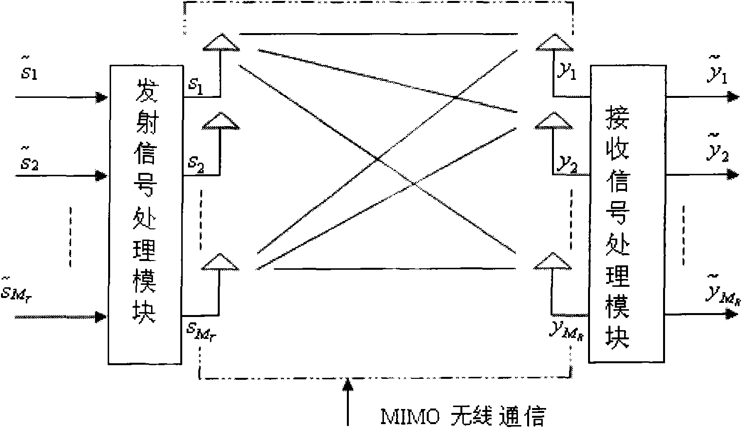
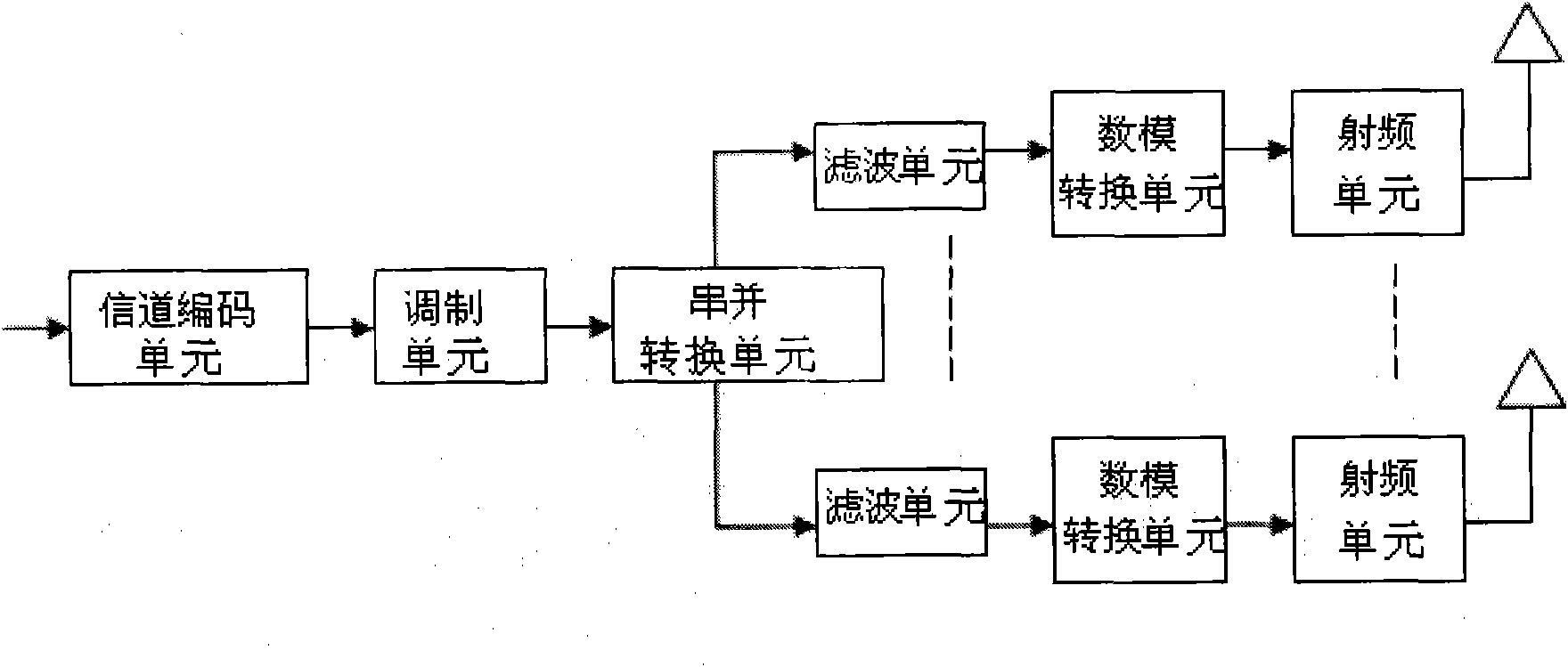
technical field [0001] The present invention relates to the field of MIMO technology, in particular to a MIMO spatial multiplexing decoding method and a MIMO spatial multiplexing decoding device. Background technique [0002] MIMO (Multiple-Input Multiple-Out-put) refers to a communication system that uses multiple transmitting antennas at the transmitting end and multiple receiving antennas at the receiving end, such as figure 1 As shown, the transmitting end includes a transmitting signal processing module and a plurality of transmitting antennas S connected to the transmitting signal processing module 1 , S 2 ......S MT , including a receiving signal processing module and a plurality of receiving antennas y connected to the receiving signal processing module at the receiving end 1 、y 2 ......y MR . The transmitted signal after modulation processing at the transmitting end After being processed by the transmitting signal processing module, it passes through the tra...

Claims


Application Information

Patent Timeline
IPC IPC(8): H04L1/06H04B7/08
Inventor 李燕苹施英
Owner COMBA TELECOM SYST CHINA LTD
Learn More