Electric-hydraulic controlled power output clutch with hydraulic brake

A technology of power output and hydraulic braking, applied in the field of tractors, can solve problems such as inability to arrange and difficult, and achieve the effect of improving service life and reliability, small size, and improving positive pressure.

Inactive Publication Date: 2010-11-24
FIRST TRACTOR
View PDF6 Cites 10 Cited by
  • Summary
  • Abstract
  • Description
  • Claims
  • Application Information

AI Technical Summary

Problems solved by technology

When the power output clutch is disengaged, the power of the engine is cut off from the shaft of the power output clutch, and devices that require uninterrupted power sources such as hydraulic pum

Method used


Image

  • Electric-hydraulic controlled power output clutch with hydraulic brake
  • Electric-hydraulic controlled power output clutch with hydraulic brake

Examples


Embodiment Construction

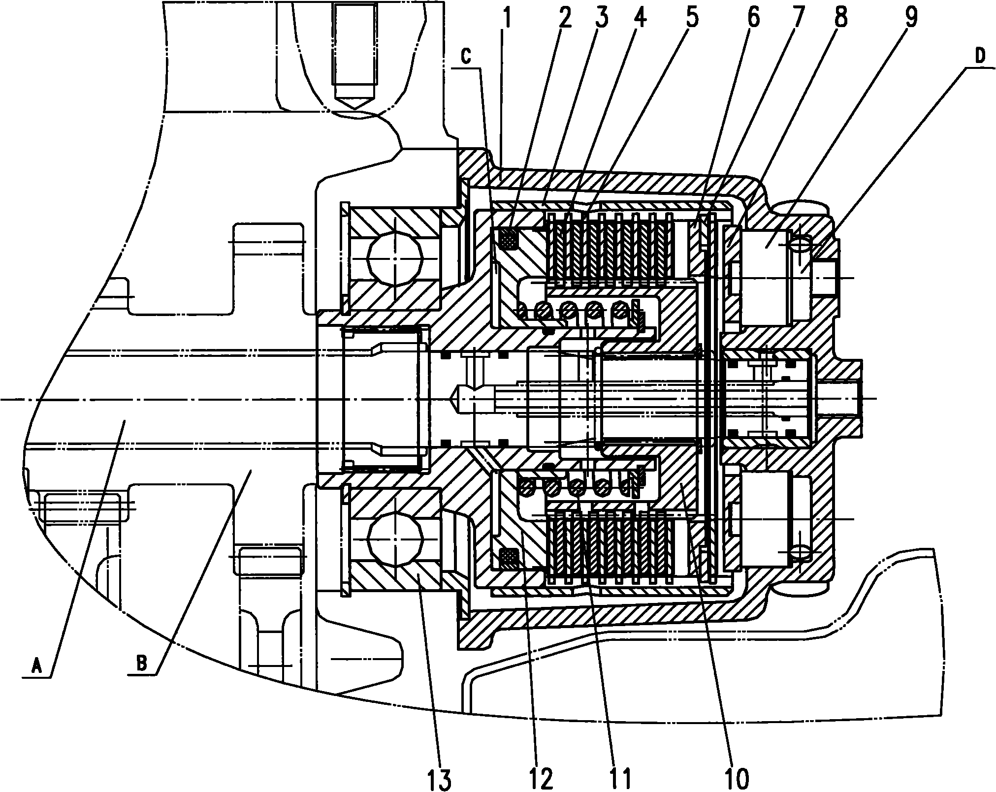
[0009] As shown in the accompanying drawings, the power output clutch device with electro-hydraulic control and hydraulic brake is mainly composed of a power output clutch housing 1, a coaxial sealing ring 2, a driven hub 3, an active friction plate 4, a driven friction plate 5, Block plate 6, circlip 7, brake friction plate 8, brake piston 9, driving hub 10, helical return spring 11, clutch piston 12, bearing 13 and so on. The driving hub 10 is keyed to the power output clutch shaft A of the tractor, and the driven hub 3 is keyed to the first shaft B of the tractor power output transmission box. Between the driving hub 10 and the driven hub 3, there are 5 to 9 pairs of driving friction plates 4 and driven friction plates 5 installed crosswise. A spiral return spring 11 is installed between the clutch piston 12 and the driven hub 3; two brake pistons 9 are installed at the rear of the power output clutch housing 1; a circlip 7 is installed at the rear of the driven hub 3, The...


PUM


Abstract

The invention relates to an electric-hydraulic controlled power output clutch with a hydraulic brake, which comprises a power output clutch housing body, a coaxial seal ring, a driven hub, a driving friction plate, a driven friction plate, a baffle plate, a circlip, a brake friction plate, brake pistons, a driving hub, a screw return spring, a clutch piston and a bearing, wherein the driving hub and a shaft A of a power output clutch of a tractor form a key joint; the driven hub and a shaft B of a power output transmission case of the tractor form a key joint; the driving friction plate and the driven friction plate are installed between the driving hub and the driven hub; the screw return spring is installed between the clutch piston and the driven hub; the two brake pistons are installed at the back part of the power output clutch housing body; and the circlip is installed at the back part of the driven hub, the front part of the circlip is provided with the baffle plate, and the back part of the circlip is provided with the brake friction plate. The electric-hydraulic control on the combination, the separation and the brake hydraulic control of the power output clutch can be realized by an electromagnetic valve, thereby facilitating the control on the combination, the separation and the brake of the clutch by using a button switch in the cab.

Description

technical field [0001] The invention belongs to the field of tractors, and relates to a tractor clutch, in particular to an electro-hydraulic control power output clutch with hydraulic brake. Background technique [0002] At present, on some high-power tractors produced in China, the power output clutch is generally integrated with the main clutch, which is a double-acting clutch installed between the engine and the gearbox. When the power output clutch is disengaged, the power of the engine is cut off from the power output clutch shaft, so devices that require an uninterrupted power source such as hydraulic pumps cannot be arranged on the gearbox. High-power tractors often require multiple hydraulic pumps to meet the needs of different functions, and it is often very difficult to install them on the engine. Therefore, setting the power output clutch device at the rear of the tractor can make the power output clutch shaft of the tractor cut off the power of the power output...

Claims


Application Information

Patent Timeline
IPC IPC(8): F16D25/062F16D25/12
Inventor 康健卢绰冯春凌王红杨桂香郭志强
Owner FIRST TRACTOR
Why Eureka
Try Eureka